Hello,
Doing my first simulations in PSUD2, could somebody explain why choke, placed closer to the recrifiers causes significant voltage drop? 10.9V and 7.6V at output, to be precise.
Thanks
Doing my first simulations in PSUD2, could somebody explain why choke, placed closer to the recrifiers causes significant voltage drop? 10.9V and 7.6V at output, to be precise.
Thanks
Attachments
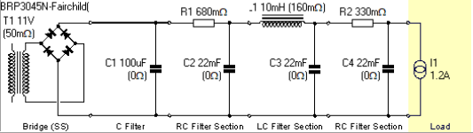
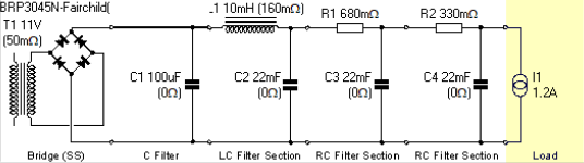
1.) There are no capacitor with 0R ESR!
2.) 50mOhm secondary DCR of PT is unreal.
3.) It's simple capacitor versus choke input filtration "problem" (100uF is nearly negligible is this case). Choke input PSU gives lower output voltage than capacitor input one.
In the first case the charging pulses of (first) 22mF generates the "raw DC" (the 100uF has larg/er/ ESR, so its charging is more lower than 22mF pulses). The limiting factor is 680mR+ESR of 22mF (few ten mOhm), so more than 2A peek pulses occurs.
In the second case the 100uF charging -current- pulses are (four times) greater, due to the choke (which has large/er/ impedance at low/er/ frequencies). The first 22mF capacitor charging pulses lower than in in first case, so the voltage also lower. BTW in this case via the choke large current flowing (steady 1.2A + 22mF charging pulses).

Thanks @euro21,
So, if struggling to reach target voltage, I can simply increase the 100uF to substantially larger (provided it has sufficient ESR rating to handle the pulses) or arrange DC board to have CRCLC configuration instead of CLCRC with no downsides? PSUD2 also shows lover voltage ripple in this case.
Regarding cap ESR -> will fix that.
As per DCR of PT - should I just measure with a good resolution multimeter?
"should I just measure with a good resolution multimeter?"
Average multimeter is inadequate for this.
Use Ohm's law:
-bench supply (or battery), series resistor (for example 10R 5-10W), coil,
BTW, what's the goal of this PSU?
LC filtering chain (if voltage is enough) causes much less load on graetz and PT, and the "first" capacitor stress (lower charging pulses) is more lower.
Average multimeter is inadequate for this.
Use Ohm's law:
-bench supply (or battery), series resistor (for example 10R 5-10W), coil,
- measure DC voltage on coil and current via it,
- DCR=U/I
BTW, what's the goal of this PSU?
LC filtering chain (if voltage is enough) causes much less load on graetz and PT, and the "first" capacitor stress (lower charging pulses) is more lower.
I have started assembling a copy of Bartola 300B and only now anticipate running into voltage problems for Coleman voltage regulators. Will be testing VT-25 and need 10.5 VDC into reg, which I am a bit short if using LC, at least according my poor PSUD2 sim. Have maximum 13V RMS available for VT-25 and 10V RMS for 300B.
https://i0.wp.com/www.bartola.co.uk...s/2020/06/300B-filament-supply-v01-scaled.jpg
https://i0.wp.com/www.bartola.co.uk...s/2020/06/300B-filament-supply-v01-scaled.jpg
The most important thing is PT capacity.
If secondary produce enough large voltage under load, it's would be usable.
Try to load secondary with appropriate resistor to load desired (AC) current, and measure AC voltage.
300B R.C. regulator (1.2A DC output) requires -at least- 9VAC/2.8A capacity power transformer.
10Y/801a requires 12VAC/2.7A (if you don't use filament bias!).
If you use smaller current capacity transformer, it will be warming.
See my posts in https://www.diyaudio.com/community/threads/801a-tube-preamp.395883/
PT’s are quite large 100VA.
My testing with CLCR…
10V RMS in -> 6.7V DC Out (RAW DC)
Regulator max outputing 5.5V to 4.3Ohm
(Closest I’ve got to 300B)
13 RMS in -> 9.37 DC Out
Regulator max outputing 8.11V to 6Ohms (Closest I’ve got to VT-25)
Will the less-than-required headroom for Coleman refulators influence the operating quality? Or better rework the RAW DC Board to be on-spec?
IMHO these raw DC values are inadequate for proper working.
R.C. regulators requires 3..5V (ask Rod for present V9 requirement) headroom over output DC (+filament bias voltage if it exist) voltage.
For 300B I use 9V raw DC, for 10Y/801a 12V.
R.C. regulators requires 3..5V (ask Rod for present V9 requirement) headroom over output DC (+filament bias voltage if it exist) voltage.
For 300B I use 9V raw DC, for 10Y/801a 12V.
Thanks on advice,
I will reshufle and will try to come up with something thats works withing the v9 regularor spec, either higher Voltage PT or different RAW DC filtering layout.
I will reshufle and will try to come up with something thats works withing the v9 regularor spec, either higher Voltage PT or different RAW DC filtering layout.

Thanks @euro21 for the tips and support - for me your comments are priceless.
Had an interesting listening test yesterday - compared the CRCRCLC filter versus a CLCLCLC filter on the 300B Pre-amplifier. Was using two 10mH and 160mR chokes (Hammond 159ZJ) and one PH9455.826NL Common mode choke (82mH and 150mR). Sonically the choke based filter sounded better. Improvements are marginal, specially when considering the ridiculous amount of iron used/costs. Also tried comparing with a simple CRC filter (Raw RC Board from Coleman) with standard 22000uF/WW 0.22R 5W/22000uF - also good, however, not as good as heavily filtered power supply.
There was also a substantial improvement (burn in?) of the new Raw DC setup within first half an hour of listening - perhaps its the capacitors settling in.
I would like to test the Actual mV fluctuation - would any standard Scope do? I have never worked with them, however, out of interest, do they run at 1mV resolution?
If you don't use filament bias, the filament voltage fluctuation -if it few mV scale- can be ignored. The inertia of the heated filament masks this.
BTW DH tubes (and filament bias resistors too -if its exist-) are sensitive to electromagnetic radiation .... some better, some less. It's more important, than filament voltage fluctuation.
BTW DH tubes (and filament bias resistors too -if its exist-) are sensitive to electromagnetic radiation .... some better, some less. It's more important, than filament voltage fluctuation.
Your circuit has very high peak currents flowing through the power transformer secondary and first filter cap - that is an area of concern for layout and noise escaping to the output of the power supply and beyond. Using physically large capacitors to further suppress noise and hum is also a concern for layout and how you interconnect them, as all the expected improvements can be easily bypassed by noise and hum by not being adequately aware.
Perhaps make sure the large e-caps are fully formed to their voltage rating first.
Perhaps make sure the large e-caps are fully formed to their voltage rating first.
Thanks for the comment @trobbins
So I understand the only option to decrease peak currents though HT Board is to use choke-loaded input filtering. A small, low ESR capacitor between rectifier and choke helps to decrease the peak currents too. The only concern is the high voltage loss compared to CRC filter. Please correct me if I am wrong here, as though my understanding and simulation I cannot find any other explanation.
I don't quite understand, I though the capacitor ripple current is the most important factor here. Appreciate if you can comment.
Sonically, I have compare two power supplies, one 7V RMS transformer, bridge rectifier, CRC filter (22uF-0.3R-22uF) and 13RMS transformer, bridge rectifier, CLCLCLC filter (100uF, 10mH, 22uF, 10mH, 22uF, Common mode 82mH, 22uF...). Both had ~8,5V at the output before the Coleman regulator. Sonically choke loaded sounded A BIT better, though its a ridiculously small improvement if considered the amount of real estate. Perhaps there is something that you would recommend to try out?
So I understand the only option to decrease peak currents though HT Board is to use choke-loaded input filtering. A small, low ESR capacitor between rectifier and choke helps to decrease the peak currents too. The only concern is the high voltage loss compared to CRC filter. Please correct me if I am wrong here, as though my understanding and simulation I cannot find any other explanation.
My power supply will be located remotely from the signal board. Still a concern?that is an area of concern for layout and noise escaping to the output of the power supply and beyond
Perhaps make sure the large e-caps are fully formed to their voltage rating first.
I don't quite understand, I though the capacitor ripple current is the most important factor here. Appreciate if you can comment.
Sonically, I have compare two power supplies, one 7V RMS transformer, bridge rectifier, CRC filter (22uF-0.3R-22uF) and 13RMS transformer, bridge rectifier, CLCLCLC filter (100uF, 10mH, 22uF, 10mH, 22uF, Common mode 82mH, 22uF...). Both had ~8,5V at the output before the Coleman regulator. Sonically choke loaded sounded A BIT better, though its a ridiculously small improvement if considered the amount of real estate. Perhaps there is something that you would recommend to try out?
Other main option is to use smaller first cap after rectifier, then LC.
Noise and hum from earlier in the power supply could still get to output of power supply when using long ladder filters.
During initial testing with new ecaps, or if the mains is a bit higher than normal, then ecaps may exhibit a relatively large forming current. Reforming an ecap to it's rated voltage (that may be significantly higher than nominal operating voltage) can alleviate unanticipated capacitor effects.
I don't listen to my power supplies unless there is noticeable magnetostriction induced buzzing.
I am completely loosing the thought here. Do you mean its benefitial to let capacitors (at least temporary, like a burn in) run on higher voltages?During initial testing with new ecaps, or if the mains is a bit higher than normal, then ecaps may exhibit a relatively large forming current. Reforming an ecap to it's rated voltage (that may be significantly higher than nominal operating voltage) can alleviate unanticipated capacitor effects.
- Home
- Amplifiers
- Power Supplies
- PSUD2 LT PSU simulation - choke placement question