I am useing PSUD2 to build a g2 supply on a 807 SE project & am haveing trouble with load on the program. Do I just use my 7k OT loading as I did with my B+ for the plates..? All resistances were measured from my chokes & such & all entered with B+ plate supply & driver supply complete. I just have never built a seprate g2 supply & don't know what to enter for load..? I have the STC data sheets for 807 on hand, a small book they are.
Thanks
Joe
Thanks
Joe
Jand G :
The g2 voltage and current should be listed on your spec sheet along with the plate vlotage and current for the SE set up being reccommended. In otherwords where did you get the plate voltage and current data ? The g2 voltage and current should be listed nearby. You mention 7K load, on the data sheet I have a 6k load is suggested with plate voltage 500 V, plate current 50 mA, g2 voltage 200, and g2 current 1.6 mA. You may want to try similar values.
Use a 1.6mA current load, or a 125K resistive load in PSUD.
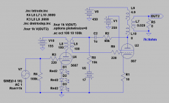
I am building this schematic & have the signal chassis done & wired & now I need to build 3 external supplies with target v's of 450v for 807 plate,250v for g2 & 155v for 5687. All will be of LCLC filters & SS bridge rectification just useing UF diodes soldered in bridge form. Just haveing trouble with PSUD2 & my brain it seems.
Joe
Joe
Attachments
You can change the load from resistor to "constant current" and fill in the 1.6 mA
The rest should be obvious...
However i do not believe the g2 voltage is very critical; do you use a separate tranformer so that the load of the output stage has no effect? If not, you could use a simple resistive voltage divider...
gr. Paul
The rest should be obvious...
However i do not believe the g2 voltage is very critical; do you use a separate tranformer so that the load of the output stage has no effect? If not, you could use a simple resistive voltage divider...
gr. Paul
Signal amp chassis is completelly built & has many umbilical sockets for external PS's. As this is a experiments amp & like bieng able to work in a non cramped enviroment. I am useing all LCLC & seperate transformers for all as I have most of the iron for this allready & want to use them up, not excludeing all the motor runs that will be in it, also to use them up. Yes I used the 1.6mA screen current & plugged that in instead . Actually plugged in 3.2mA for both tubes. I will probablly regulate the g2 with simple VR shunt reg tubes as I am not up on regulation schemes. Thanks for the help
Joe
Joe
- Status
- Not open for further replies.