Hi,
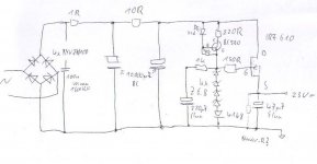
attached is a simple but hopefully good (in relation to parts count) PSU that I plan to build. Only positve rail shown.
The quality of the attachment is bad (is there a fast&easy freeware circuit painter out there?), I hope you can read it.
My goal is to have a reasonable quiet and sonically well performing PSU, or the best what can be made out of that few components.
Is there something missing, any mistakes? What do you think of the ccs feeding the zeners (it's in fact cheaper than a current diode).
Rüdiger
Attachments
Hi,
why 4*6.8V instead of 27V?
Why the 1k0 before 220uF elna?
Why use a plastic cap at the start of the RCRCRC string.
I think you would get better audio performance if the plastic cap was either at the end of the string or replaced the 47uF output cap. That 1600V 100uF must be as big as a car battery and cost the same as the car it fits in!
Can you modify your 1 (one) script, it is very ambiguous?
Yes, indeed.Tweeker said:I think thats 100nF 1600V.
I have a few hundred 6.8V Zeners, thats why...
I made a quick sketch of this but used only 3x6.8Z, because I found only a 18 VAC Transformer in my bin.
The 1k/220uF String is for filtering zener noise.
It works so far, now I need the negative rail.
How big can the output Cap (now 47uF) get, is there a upper limit?
Not sure what you meanAndrewT said:
Can you modify your 1 (one) script, it is very ambiguous?

Rüdiger
Onvinyl said:
The 1k/220uF String is for filtering zener noise.
Hi Rüdiger
For that purpose , the 150 Ohms resistor that come from the gate of the Mos-fet must be connected to the junction point of the 1K Resistor with the 200uF capacitor. This is what Technics call "Virtual Battery Operation".
The resistor that bias the LED must be connected between the base of the BC 560 and ground , that way the transistor could behave as a CCS.
Regards.
Tube_Dude said:
Hi Rüdiger
For that purpose , the 150 Ohms resistor that come from the gate of the Mos-fet must be connected to the junction point of the 1K Resistor with the 200uF capacitor. This is what Technics call "Virtual Battery Operation".
The resistor that bias the LED must be connected between the base of the BC 560 and ground , that way the transistor could behave as a CCS.
Regards.
Ok, I'll fix it. But, since the thing works as it is, how does the transistor behave now?
Regs,
Rüdiger
Onvinyl said:
Ok, I'll fix it. But, since the thing works as it is, how does the transistor behave now?
As a CCS with a resistor in parallel ...😉
Putting another way...a very bad CCS.

Hi,
i think you will waste a lot of power with this PSU.
For linear operation up to 1A the IRF610 needs a VGS of about 6V. The CCS needs at least 2V to stay in regular operation.
At higher currents the 10R-resistor will consume some voltage too.
Added you need an input voltage of about 30V to achieve a 23V output. That seems to much for me. Do you have to use this FET? A BJT wold do a better job here, because the staple of zeners can only be adjusted to a certain operation point and the output voltage will vary with the current.
For better drawings (and simulation) you may download switchercad III from:
http://www.linear.com/company/software.jsp
It´s a free spice without restrictions and very common.
Onra
Put the N-channel MOSFET in the negative side and use a PNP transistor with its base connected to the negative (regulated) output, the emitter connected to the positive (fixed) output through a suitable zener and resistor, and its collector driving the gate with a bleeder resistor to the negative unregulated input. I've employed that kind of regulator in the past and it works fine, not to talk about its awesome simplicity and the convenient grounding of the tab of the power MOSFET.
Hi Eva,
you're giving me a hard time...
Are you talking about something like
borbely link see Page 5 with Q2 and Q4 omitted? Seems to be very cool indeed!
Rüdiger
you're giving me a hard time...
Are you talking about something like
borbely link see Page 5 with Q2 and Q4 omitted? Seems to be very cool indeed!
Rüdiger
Something like that, but with a bipolar transistor driving the MOSFET. It yields very good performance for a 7 part discrete design...
Well, you just mentioned 5. I guess you need a resistor from Drain to Ground and a feedback res between Drain and Base?Eva said:Something like that, but with a bipolar transistor driving the MOSFET. It yields very good performance for a 7 part discrete design...
You don't happen to have a schematic handy? I'm eager to try it out!
@Onra:
The Mosfet was in my parts bin. Some people reported a sonically well performance, I'll try it out. It's clear to me that a non 3-pin regulator should sound better than say a LM317, else it makes no sense to try other options. So, if you know a good bjt suitable for this job, just tell me...
Another option to try would be the TL431 as a reference.
thanks,
Rüdiger
Hi,
there is a similar basic circuit i found at:
http://www.mikrocontroller.net/attachment.php/269832/Schaltung.png
You can use a P-MOSFET instead of the darlington power stage.
Voltage is controlled by the Resistor divider across the output.
To improve regulation (?) and output noise you can try a LED instead the zener.
The negative rail is then mirrored with respect to the polarity of active devices.
I asked for the need of IRF610 because of its high RDSOn and low current capability.
What is your current range the PSU should supply?
Onra
[voice from off:] What is suitable for around 24V?Eva said:...output through a suitable zener and resistor...
I do not really get what happens there.
Rüdiger
I made a quick breadboard. With +/- 12Vin all goes fine, with 8Vout.Onvinyl said:
I do not really get what happens there.
Rüdiger
I used a 6.8V Zener, BC550/560, and IRF(9)610.
With +/- 24Vin one of the bipolars explodes, even with 13.6V Zener. I have no clue why, since I see no exeeding of voltages.
😕
Rüdiger
Hi Onvinyl,
you are calling up both pnp & npn transistors.
Which schematic did you use?
That one in post1 is wrong.
you are calling up both pnp & npn transistors.
Which schematic did you use?
That one in post1 is wrong.
- Status
- Not open for further replies.
- Home
- Amplifiers
- Power Supplies
- PSU with Simple Source Follower Regulator