Hi...
I want to try to create my very first PSU, and I'm just a very newbie.
First this is want i would like to archeive..
1) Only using the ClarityCap TC caps in this Design.
2) Limit the use of Capacitors to get an acceptable level of ripple.
3) use a choke to limit Capacitors values.
4) I have some limited space so I cant use more than 1 choke...
I'm using PSUD2 and have some questions.
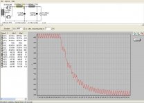
My homemade PSU design has some kind of ringing the first up to 2 seconds.
Is this a problem, I'm using a soft start delay at a least 40 seconds.
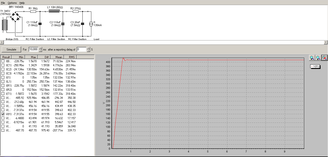
Ringing
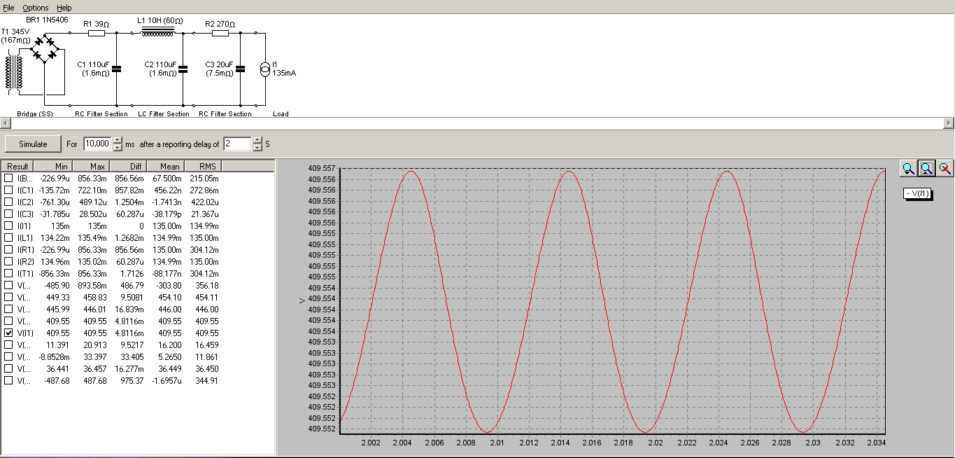
Quite stable after 2 sec.
/Thanks Michael
I want to try to create my very first PSU, and I'm just a very newbie.
First this is want i would like to archeive..
1) Only using the ClarityCap TC caps in this Design.
2) Limit the use of Capacitors to get an acceptable level of ripple.
3) use a choke to limit Capacitors values.
4) I have some limited space so I cant use more than 1 choke...
I'm using PSUD2 and have some questions.
My homemade PSU design has some kind of ringing the first up to 2 seconds.
Is this a problem, I'm using a soft start delay at a least 40 seconds.
Ringing
Quite stable after 2 sec.
/Thanks Michael
Last edited by a moderator:
Put chokes and capacitors together and you have the potential for ringing. A lower quality choke with higher resistance would damp it down a bit. Also, the actual load may be more like a resistor than a CCS so that would add some damping.
Hi,
If I have done the maths right, the frequency of this "ringing" is 100Hz. Which is the frequency of the rectified mains.
The amplitude is only 5mV pk-pk.
I would not worry about it.
CHeers,
Serge
If I have done the maths right, the frequency of this "ringing" is 100Hz. Which is the frequency of the rectified mains.
The amplitude is only 5mV pk-pk.
I would not worry about it.
CHeers,
Serge
Or are you talking about the overshoot at about 0.5s. They are difficult to tame. Small capacitor (10-100nF) on both sides of the choke to ground.
Cheers,
Serge
Cheers,
Serge
I think I managed to build a better circuit.
Here is the new one.
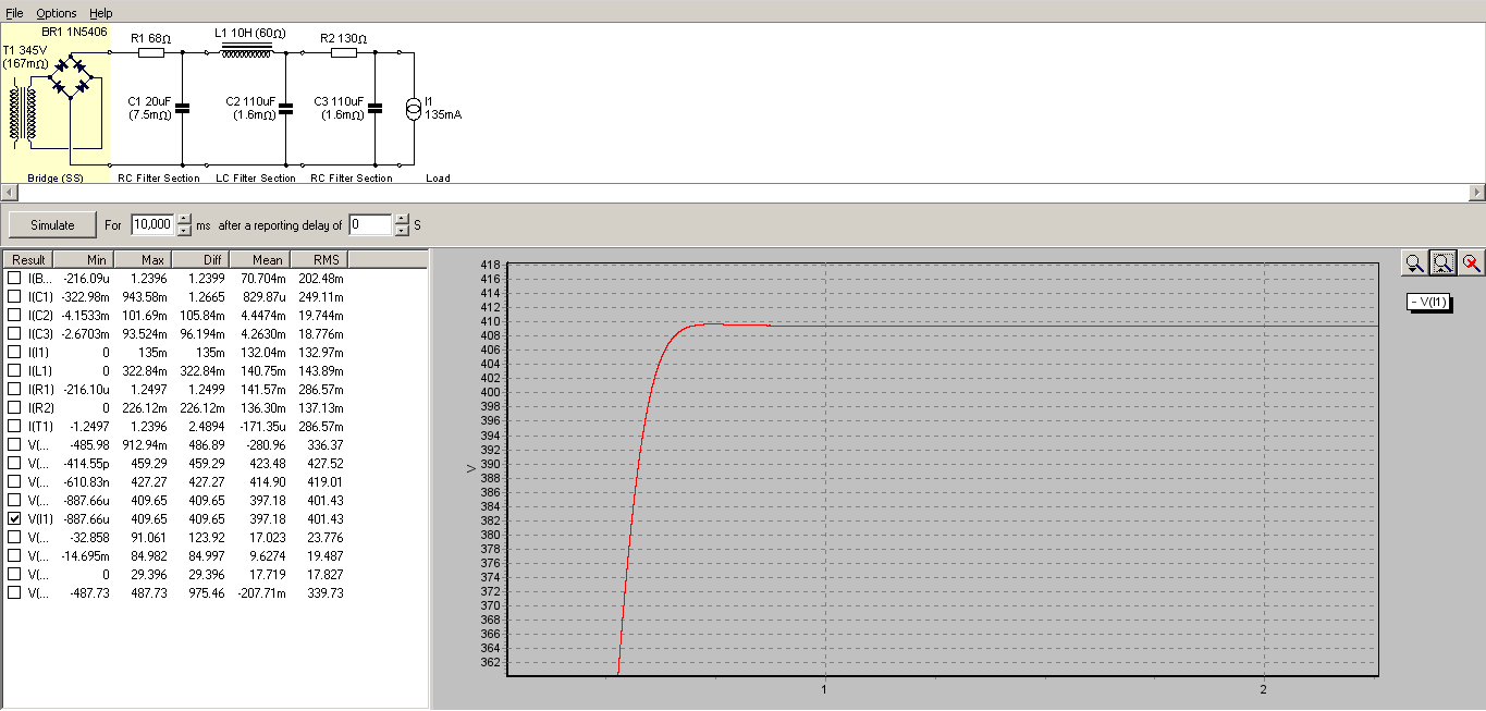
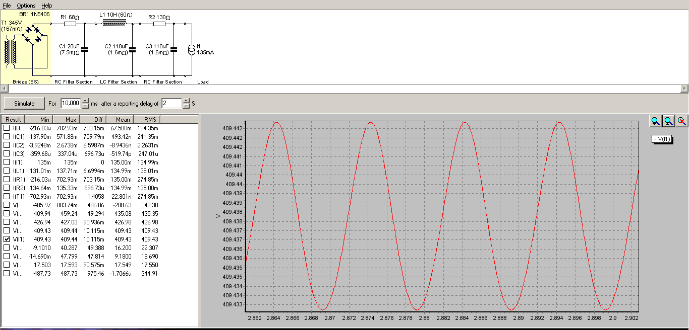
And simulation after 2 seconds.
/Michael
Here is the new one.
And simulation after 2 seconds.
/Michael
Hi,
I have been building the Loftin White "inspired" amps you discuss for some time now, over ten years.
I hope people do not copy your first attempt at a power supply, shown above !!
Here are some (hopefully) helpful suggestions I would like to propose:
1) In lieu of Clarity Caps, in 2016 we can use industrial-priced WIMA DC LINK caps to great effect, they sound wonderful, order their 4 LEAD ones, not two lead
2) Low ripple you obtained ( 4.81 mVAC ) is NOT the design goal to 2A3 Finals, never was, never is !! You can have up to 800 mVAC of ripple to the 2A3 plate, and it will be fine.
You want low ripple to the high mu Driver tube in a two stage amp, usually 2 mVAC or less. A simple R/C network, after the current-hungry Finals stage, to feed the Driver stage, neatly accomplishes this.
3) You need to use a tube rectifier, to avoid turn-on problems with the various tubes. I prefer the sonics of directly heated rectifiers.
4) The design goal and the KEY requirement to a tube amp's power supply filter, especially for a 2A3 type tube, is to have as LOW of a series resistance in the B+ filter as possible, feeding the 2A3 Finals stage.
Your two PSUD examples' total "roughly" 369 Ohms and 258 Ohms of series resistances, I would highly suggest you look carefully to see how I reduced it to "roughly" 22 Ohms.
5) Use an "L" input filter, immediately after the rectifier tube. It need not be L-Critical at all. Use two L/Cs in series, to achieve DCR and filtering goals to the Finals
5) Power Supply capacitors sound best to me, and others, when they are small in value. I prefer 50 uF as a maximum. When caps are larger than 50 uF, under dynamic conditions, the low impedance caps get re-charged from the supply, AHEAD of the 2A3 tube. This results in lessened dynamic contrasting at the loudspeaker, and always a more " canned " sound from the amp.
6 ) The effective DCR of the power transformer in your PSUD simulation is 167 milliOhms. That is an impossibility.
7) You want closer to 450 VDC ( to as high as maybe 490 VDC ) of B+ in a two stage DC amplifier. Your simulated B+ is too low, it compromises the Op Points of the two tubes.
The PSUD shot I am posting is a "worst case" implementation. The Chokes are 159Y Hammonds, 600 mHY at 11 Ohms, less than $30.00 each. The bare minimum is to use two for a stereo amp, they are NOT large, fit under the chassis.
With two L/Cs ( as in L1/C1/L2/C2 ), ripple to the 2A3 Finals stage will be under 800 mVAC.
Want lower ripple to the 2A3?? A better topology is to use " one " shared L1/C1, into a "Y" with a separate L2/C2 for each channel.
An even better topology, and what I like, is a L1/C1/L2/C2 for each channel of a stereo amp.
Best yet is a Dual Mono Stereo Amp, or two monoblocks, provides the utmost in clarity.
One other important thing, we can PSUD2 supplies till you are blue in the face, trying to optimize and trade-off conflicting goals. You can EASILY get a better PSUD screen shot than what I have posted. My challenge is this " Will it SOUND better " than what I have suggested here in this post. "I" think not !! Try it and let me know what you hear ! 🙂
There is no free lunch. In the end, we all listen to a modulated power supply. How good is yours ??
Jeff Medwin
Attachments
Last edited:
The reason the PSU caps are there is to ensure that they get "re-charged from the supply" ahead of the rest of the circuit. I find it hard to attach meaning to what appears to be a complaint that the circuit is doing exactly what the circuit is supposed to do.drlowmu said:5) Power Supply capacitors sound best to me, and others, when they are small in value. I prefer 50 uF as a maximum. When caps are larger than 50 uF, under dynamic conditions, the low impedance caps get re-charged from the supply, AHEAD of the 2A3 tube. This results in lessened dynamic contrasting at the loudspeaker, and always a more " canned " sound from the amp.
Note that, to a first approximation, the effective DC resistance of a PSU cap which gets recharged regularly from a full-wave rectifier is 1/(4 f C). If you want low supply rail impedance then the caps should not be too small. One of the advantages of a choke input supply is that the cap value is not constrained by the rectifier, as it is for a cap input supply.
The reason the PSU caps are there is to ensure that they get "re-charged from the supply" ahead of the rest of the circuit. I find it hard to attach meaning to what appears to be a complaint that the circuit is doing exactly what the circuit is supposed to do.
Note that, to a first approximation, the effective DC resistance of a PSU cap which gets recharged regularly from a full-wave rectifier is 1/(4 f C). If you want low supply rail impedance then the caps should not be too small. One of the advantages of a choke input supply is that the cap value is not constrained by the rectifier, as it is for a cap input supply.
Please see any ( and all ) of EE "JLH"s writings on the Audio Asylum in 2009 - 2010.
Start with this :
You?re neglecting the behavior of capacitors. - JLH - Tube DIY Asylum
Also, please read his " Dynamic Impedance " post of July 1. 2009.
Then you will have it.
Our listening results, past 15 years, trump the OLD theory. Results do count the most !
Respectfully,
Jeff
Last edited:
That is complete garbage. If the cap can't recharge then it can't provide current in the future. I'm sure a badly designed PSU feeding a SET sounds different from a well-designed PSU feeding a SET; I'm less sure why some people may prefer the bad one.drlowmu said:Start with this :
You?re neglecting the behavior of capacitors. - JLH - Tube DIY Asylum
If you want to optimize your power supply, start with this:
http://www.diyaudio.com/forums/powe...using-quasimodo-test-jig-106.html#post4880028
http://www.diyaudio.com/forums/powe...using-quasimodo-test-jig-106.html#post4880028
 OT posts deleted, attack the ideas not the person.
Yes, but these larger capacitors reduce the rail variations at their source. They play the part of the low impedance.When caps are larger than 50 uF, under dynamic conditions,
If this final supply capacitor(s) is fed from an inductor (not that it necessarily should be) the capacitor can be topped up with DC while being isolated as the stage supply.
Yes, but these larger capacitors reduce the rail variations at their source. They play the part of the low impedance.
If this final supply capacitor(s) is fed from an inductor (not that it necessarily should be) the capacitor can be topped up with DC while being isolated as the stage supply.
Yes, but think dynamically, when the supply has to do a transient, and the cap is drained, it "goobles up" the fresh charge, and short-changes the higher Z 2A3, reducing dynamics that the tube can ( and should ) replicate at the speaker.
Do this, go over to the Audiio Asylym, and look up EVERY post JLH ( John Hasquin ) wrote from 2008 to 2010 on this subject. Or, EASIER - email me and I will send you a chronological compilation, of both EEs John Hasqin and John Swenson, who did a GOOD job on this subject !!
Its a new and more modern, more inclusive understanding of what is going on, and its correct in theory and, most important to me, in practice !!
Jeff drlowmu@gmail.com
Ask me for "Chronological Posts",.... I compiled it to help people understand.
With the larger capacitor the 'extra charge' was collected prior to the transient. The ultimate indicator of the magnitude of the effect of the transient can be brought down to the rail variations which will be reduced.Yes, but think dynamically, when the supply has to do a transient, and the cap is drained, it "goobles up" the fresh charge, and short-changes the higher Z 2A3
Yes, a low impedance supply source can do this as well. As a side argument this method would bring more of the supply into the signal path.
No, think electronically. The supply does not "do transients"; the cap does transients, so the bigger the better (within reason). This is especially true for a choke input supply.drlowmu said:Yes, but think dynamically, when the supply has to do a transient, and the cap is drained, it "goobles up" the fresh charge, and short-changes the higher Z 2A3, reducing dynamics that the tube can ( and should ) replicate at the speaker.
There is a way that a small cap might give the false impression of better dynamics. SET amps tend to be low power, and so have to be run nearer their maximum power. This means significant amounts of 2nd order distortion, which cause increased average supply draw on music peaks. A smaller cap will give more sag, so the supply rail voltage will vary more. Now many SET fans don't believe in feedback, so the amp gain will depend on rail voltage. Hence the music signal is being modulated to some extent by a slightly delayed version of its own envelope. This could appear to some people to be improved dynamics, when in fact it is a form of intermodulation. If they get used to this then a more accurate amp which simply amplifies the music may seem to be lacking in something.
With the larger capacitor the 'extra charge' was collected prior to the transient. The ultimate indicator of the magnitude of the effect of the transient can be brought down to the rail variations which will be reduced.
Yes, a low impedance supply source can do this as well. As a side argument this method would bring more of the supply into the signal path.
You act and think as though the supply is separate from the audio amp !!
In a amplifier such as a SET 2A3 amp, the supply IS IN THE AUDIO Path. In the end, we " all listen to a modulated power supply " How good is it ??
You really need to simply read and digest the two compilations I offered, by EEs Hasquin and Swenson, as they explain this quite well !! Just write to me, then you will understand better, as I will promptly forward it to you.
Jeff
I'd ask for some measurement results that show that using smaller capacitors increases "dynamic contrasting," but I have a sneaking suspicion that this is one of those things that can only be measured with someone's "golden ears" and can only be explained by an appeal to authority.
You act and think as though the supply is separate from the audio amp !!
In a amplifier such as a SET 2A3 amp, the supply IS IN THE AUDIO Path. In the end, we " all listen to a modulated power supply " How good is it ??
Jeff
Well, I can't know DF96's mind, but this is what he said:
"A smaller cap will give more sag, so the supply rail voltage will vary more. Now many SET fans don't believe in feedback, so the amp gain will depend on rail voltage. Hence the music signal is being modulated to some extent by a slightly delayed version of its own envelope. This could appear to some people to be improved dynamics, when in fact it is a form of intermodulation."
Quite clearly he is saying that the power supply "is" part of the audio path (though I'm only guessing what the informal term "audio path" means). And if one draws the current loops, it's visibly apparent. BTW, in the true Loftin/White, the output current does not circulate through the power supply, so the supply can be said to be largely out of the "audio path".
Sheldon
- Status
- Not open for further replies.
- Home
- Amplifiers
- Tubes / Valves
- PSU with Choke for Loftin-White 2A3