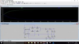
Hi,
I'd like to simulate this PSU in PSU Designer II but I don't seem to be able to recreate the same type of spit supply with ground in the middle. Does anyone know if this is possible at all and if not if I can at least partially simulate it?
Or failing all that is there some more advanced software that would allow me to do this?
Thanks.
Attachments
I don't think PSUD2 can do this. You need some version of Spice.
You could use PSUD2 to simulate half of this.
You could use PSUD2 to simulate half of this.
Of course -that's what SPICE was designed for. Use LTSPICE, PSPICE or TINA TI; they are infinitely more powerful than PSUD.Or failing all that is there some more advanced software that would allow me to do this?
Last edited:
Thanks. I suspected I might have to go the Spice route. Is there any particular version that's particularly good for simulating valve gear?
AND… don't forget… LTSpice may well be the ONLY SPICE in the world that works equally well on both Macs and PCs. I - being both an erstwhile PC and a 'humbled' MAC user - appreciate this kind of thing.
GoatGuy
GoatGuy
I think LTspice is the most popular (and free). Click my signature line for details of how to get started.
Here is the file for the power supply if you want a play.
I've managed to get LTSpice running and I've run a simulation on the file you made. However it looks like the circuit is being simulated with no current draw. How do I tell it that the PSU has 120mA being drawn from it like I would with the constant current load option is PSU Designer II?
Thanks.
Use a resistor across the output of about the right size. Adjust the ohmage when the current/voltage is shown. It shouldn't take more than a few minutes. GoatGuy
[edit... I took out the "use a current source" recommendation since it can cause all nature of convergence problems with some configurations of components.]
[edit... I took out the "use a current source" recommendation since it can cause all nature of convergence problems with some configurations of components.]
Last edited:
Ok, so the PSU is supposed to deliver about 200V across the output (using a 125-0-125V transformer) and the current draw of the load is about 120mA. So I would guess I need to use Ohm's law to calculate that I need a 1.6k resistor to get that current. But when I do that in LTSpice I get about 76V and 48mA. 
What am I doing wrong? 😕

What am I doing wrong? 😕
Lets build it up in stages.
A 125 volt transformer is actually an rms value (125 vrms) and the way LT works is in peak voltages. So we set the two voltage sources to give the peak voltage which is around 176 volts (125*1.414 which is 176).
If you right click each voltage source you can change the peak amplitude from 100 to 176.
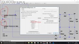

Here is a new file with current sinks as 'active' loads.
You mentioned 120ma and and 200 volts across the load. A 125 vrms tranny will give around 176 vdc which is the most you can generate 'per rail'. So yes, you have 350 volts + available as a total, but that is rail to rail and not ground to each rail.
This file has the current sinks set to 120ma and if you run the file you will see you end up with around half a volt across each... which is to be expected when fed from two 820 ohms per rail. So the simulation is showing the reality.
Edit... I'm not explaining it very clearly. The two current sinks haven't got enough current being applied to them via the 820 ohms in order to get the sinks to limit out at the set value (120ma).
(Is there any reason you are not using a reservoir cap directly after the bridge ?)
Attachments
Thanks, the transformer voltage situation makes sense.
Just to point out, R1,2,3 and 4 should be 330R.
I tried your updated file and it now seems even worse than before. Now I'm getting less than 2V on the output.
From what I've read the total load across the output should be 120mA but you have 120mA on either side. So I don't know what difference that will make. I tried changing back to a resistor load and that still isn't right either. So I don't understand what's going on.
I'm not sure why there's no input cap. This is a design I found online HERE. The schematic says that chokes can be used instead which would make more sense and that's why I wanted to run some simulations to see how much difference chokes make. I was also quite shocked at the value of the caps as I'm used to seeing much smaller caps in tube amp supplies but I guess the voltage is quite low compared to a power amp.
Just to point out, R1,2,3 and 4 should be 330R.
I tried your updated file and it now seems even worse than before. Now I'm getting less than 2V on the output.

From what I've read the total load across the output should be 120mA but you have 120mA on either side. So I don't know what difference that will make. I tried changing back to a resistor load and that still isn't right either. So I don't understand what's going on.
I'm not sure why there's no input cap. This is a design I found online HERE. The schematic says that chokes can be used instead which would make more sense and that's why I wanted to run some simulations to see how much difference chokes make. I was also quite shocked at the value of the caps as I'm used to seeing much smaller caps in tube amp supplies but I guess the voltage is quite low compared to a power amp.
Shoot, you guys!
[1] stop using current sources. They have very specific uses, and their use can often result in simulations that do not converge on useful numbers. "Just say 'no!'"
[2] get back to basics … The first set of resistors following the rectifiers should be from 50 to 150 Ω. No more. Or even eliminated.
[2b] The capacitor values are fine.
[2c] The voltage sources should be 176 volts.
[2d] Given that the output will be about 165 - 0 - 165 (split), then the individual resistors at the end should be 1.3 kΩ each. This will draw 120 ma at 160 volts. NOTE that you also need to change ALL the "internal" resistors to 50 to 100 Ω instead of 820.
Then it should work just fine in simulation.
REMEMBER - voltage sources are safe for simulation. CURRENT sources are quixotic and can cause willy-nilly use to fail to numerically converge, resulting in "crâp" values. They are not for newbies. (But, in the hands of experienced people, they're absolutely vital for modeling complex transistor, tube and FET dynamics. Just saying: they're like playing with swords… easy to get cut. )
GoatGuy
Good advice ^
This isn't making sense on the power supply front...
The article specifies a 125-0-125 volt transformer. To set that up in LT we calculate the peak voltage which is 176. That's an absolute.
Where does this 120ma come from ? The circuit shows 12 individual stages, all with 11k cathode resistors. Assuming each stage has the cathode at 0 volts then we have a current draw of (100/11000)*12 which is 110ma, OK lets say 120ma all in.
Next up and he says that the circuit is running at -/+100 volts (or 200vdc in total)
So lets now set the simulation up to emulate that. The load has to be 200/0.12 which is 1.666k in total. For our split supply that means 833 ohms per rail.
Check the maths. V supply is 100 volts. I = 0.12 amps R = approx. 833 ohms
Plugging these numbers into the simulation and we need around 91 ohms for the four resistors. They would need to be at least 2 watt rated.
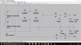
Here are the voltages and the load current (load current scale shown at the right).
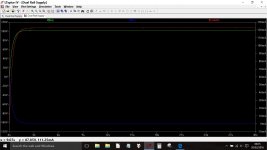
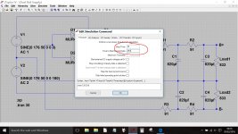
If you now edit the simulation (right click the schematic and select Edit Simulation CMD) and change the time it starts saving data to 29.8s then you can look at the ripple.
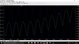
This is showing the ripple voltage of B+ and the current in R2. You can see that even after 30 seconds that there is still a definite slant to the voltage... its still not stabilised. Try setting the sim for 300 seconds in total and to start saving data at say 299.6. The sim will take a few seconds to run, the progress is shown at the bottom left.
This isn't making sense on the power supply front...
The article specifies a 125-0-125 volt transformer. To set that up in LT we calculate the peak voltage which is 176. That's an absolute.
Where does this 120ma come from ? The circuit shows 12 individual stages, all with 11k cathode resistors. Assuming each stage has the cathode at 0 volts then we have a current draw of (100/11000)*12 which is 110ma, OK lets say 120ma all in.
Next up and he says that the circuit is running at -/+100 volts (or 200vdc in total)
So lets now set the simulation up to emulate that. The load has to be 200/0.12 which is 1.666k in total. For our split supply that means 833 ohms per rail.
Check the maths. V supply is 100 volts. I = 0.12 amps R = approx. 833 ohms
Plugging these numbers into the simulation and we need around 91 ohms for the four resistors. They would need to be at least 2 watt rated.

Here are the voltages and the load current (load current scale shown at the right).

If you now edit the simulation (right click the schematic and select Edit Simulation CMD) and change the time it starts saving data to 29.8s then you can look at the ripple.

This is showing the ripple voltage of B+ and the current in R2. You can see that even after 30 seconds that there is still a definite slant to the voltage... its still not stabilised. Try setting the sim for 300 seconds in total and to start saving data at say 299.6. The sim will take a few seconds to run, the progress is shown at the bottom left.

You may also want to put in some parasitic resistance (I use 0.2 ohms) in the voltage sources. Otherwise you may find you get extremely unrealistic charging currents in your caps 🙂
Tony.
Tony.
- Status
- Not open for further replies.
- Home
- Amplifiers
- Power Supplies
- PSU simulation help

