hi,
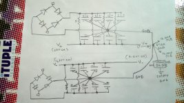
After struggling to do a DIY board, I have decided to use wire. I am attaching how I am going to assemble F5T V2 (PSU from F5 manual), please let me know if you see any major flaw.
I have a hard time visualizing circuits, so wanted someone to ok.
Thankyou
After struggling to do a DIY board, I have decided to use wire. I am attaching how I am going to assemble F5T V2 (PSU from F5 manual), please let me know if you see any major flaw.
I have a hard time visualizing circuits, so wanted someone to ok.
Thankyou
Attachments
Last edited:
Have another look at the schematic in the manual, it doesn't use two bridges, it uses diodes in parallel, there is only one bridge. That's just for starters 😉🙂
Ok, in that case you could build two separate supplies, one for each rail and connect them in series at the output, is that what you have tried to do in your diagram? It looks like it, it's just a slightly confusing way of drawing it, but it is basically correct.
Last edited:
If I connect in series V+, V- will only be at one end and not at same distance from amp PCB's. My transformer has large diameter and thinking of placing them horizontally like this (. are caps , above that is big transformer, X- space)
___________
|TTTTTTTTTT|
|TTTTTTTTTT|
|RRRRRRRRR|
|ANSFORMER|
|XXX....XXXX|
|XXX....XXXX|
|XXXXXXXXX|
i'll lay one over the other(exactly as shown in attachment) so :
1. They are at same distance from both amp PCB's. I have V+, V- on both sides for left and right amp PCB.
2 So I can twist V-, V+ and GND which goes to amp PCB left and right.
Last edited:
When I say in series I mean from an electrical point of view, not a physical one, not that the relative distances to the amp boards are an issue.
Electrically it just means the negative rail of one supply is connected to the positive of the other to create the 0V rail, as you have done
Those who have used wire to connect PSU caps, what do you use to insulate(electrically) caps from base plate and still thermally conductive?
Mica Glass came to mind but it would easily crack.
Any suggestion?
Mica Glass came to mind but it would easily crack.
Any suggestion?
no need for thermal conduction
Thankyou,
In that case I'll just use a ceramic tile that wont break easily.
- Status
- Not open for further replies.
- Home
- Amplifiers
- Pass Labs
- PSU Query