Hello PSU gurus,
I am not a psu kinda guy, so wanted some input. I recently acquired the above dac for short money and wanted to play. Unfortunately, I no one has the schematic - not even Monster who made the stuff!
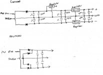
One of the things I'm hoping to do is a PSU mod. The current setup is an ite rated walwart putting out 16v ac. It plugs into the case via standard size N coax plug. Rectifying is done on board.
My problem with the current setup is that it takes the pin leg of the walwart to create the + and - for various portions of the circuit, and uses the shield leg for the ground. The + and - then goes to different sections, each with it's own regulator pair (lm7815 and lm7915 for example).
The pin leg goes to 2 diodes, one for + and one for -. It is therefore half-wave rectification which, to me is half-*** rectification causing larger ripple, etc.
I was thinking that I could 'tap' into the shield leg, with 2 more diodes to the + and - thereby creating full rectification (hmmm...the more I type out the word, the wierder it sounds😀 ).
Would this be a some kind of problem as far as grounding, noise, etc.? Or should I get a ct tranformer, take the two legs through a bridge or 4 diodes for the + and -, and use the ct for the ground?
If it helps, I have attached a drawing of the current setup and my proposed setup. Sorry, I'm not up to snuff at drawing schematics.🙁
Any help greatly appreciated!
Wayne
I am not a psu kinda guy, so wanted some input. I recently acquired the above dac for short money and wanted to play. Unfortunately, I no one has the schematic - not even Monster who made the stuff!
One of the things I'm hoping to do is a PSU mod. The current setup is an ite rated walwart putting out 16v ac. It plugs into the case via standard size N coax plug. Rectifying is done on board.
My problem with the current setup is that it takes the pin leg of the walwart to create the + and - for various portions of the circuit, and uses the shield leg for the ground. The + and - then goes to different sections, each with it's own regulator pair (lm7815 and lm7915 for example).
The pin leg goes to 2 diodes, one for + and one for -. It is therefore half-wave rectification which, to me is half-*** rectification causing larger ripple, etc.
I was thinking that I could 'tap' into the shield leg, with 2 more diodes to the + and - thereby creating full rectification (hmmm...the more I type out the word, the wierder it sounds😀 ).
Would this be a some kind of problem as far as grounding, noise, etc.? Or should I get a ct tranformer, take the two legs through a bridge or 4 diodes for the + and -, and use the ct for the ground?
If it helps, I have attached a drawing of the current setup and my proposed setup. Sorry, I'm not up to snuff at drawing schematics.🙁
Any help greatly appreciated!
Wayne
Attachments
wtyamamoto said:Hello PSU gurus,
I am not a psu kinda guy, so wanted some input. I recently acquired the above dac for short money and wanted to play. Unfortunately, I no one has the schematic - not even Monster who made the stuff!
One of the things I'm hoping to do is a PSU mod. The current setup is an ite rated walwart putting out 16v ac. It plugs into the case via standard size N coax plug. Rectifying is done on board.
My problem with the current setup is that it takes the pin leg of the walwart to create the + and - for various portions of the circuit, and uses the shield leg for the ground. The + and - then goes to different sections, each with it's own regulator pair (lm7815 and lm7915 for example).
The pin leg goes to 2 diodes, one for + and one for -. It is therefore half-wave rectification which, to me is half-*** rectification causing larger ripple, etc.
I was thinking that I could 'tap' into the shield leg, with 2 more diodes to the + and - thereby creating full rectification (hmmm...the more I type out the word, the wierder it sounds😀 ).
Would this be a some kind of problem as far as grounding, noise, etc.? Or should I get a ct tranformer, take the two legs through a bridge or 4 diodes for the + and -, and use the ct for the ground?
If it helps, I have attached a drawing of the current setup and my proposed setup. Sorry, I'm not up to snuff at drawing schematics.🙁
Any help greatly appreciated!
Wayne
HI.
Your proposed layout is in fact no different !
The 2 extra diodes do nothing.
You would require a centre tapped transformer to get full wave rectification.
Andy
A tranny with a secondaries will provide full rectification in diode bridge form...
see
http://ourworld.compuserve.com/homepages/g_knott/elect207.htm
In this case I would just build a good psu in an case ....full wave rect. voltage regs and filtering caps etc.....there are endless designs that will out perform the jobie fitted.
see
http://ourworld.compuserve.com/homepages/g_knott/elect207.htm
In this case I would just build a good psu in an case ....full wave rect. voltage regs and filtering caps etc.....there are endless designs that will out perform the jobie fitted.
Andy,
The shield of the coax power connector is attached to the other leg of the transformer. Would that not capture the ac swinging the other way through the other diodes?
Zanash,
I am seriously considering a whole outboard power supply in a seperate case cuz there's not much room on the board to fool around...
Thank you both for your inputs!
Wayne
I know this is a terribly old thread, but I was curious if any progress had been made on the external PSU? I recently picked one of these up and had planned a few mods. LM4562 to replace the OPA2134 opamp, some recapping of the generic nichicon caps (leaving the nichicon muse in place) and possibly a new full wave rectification stage and possibly and external PSU. If you have any new information, i'd love to hear about it.
the opa2134 is pretty good .....
I got rather good results from fitting good output sockets and better decoupling caps in the output.
I swapped the diodes for schottky's 11dq10's as thats all I had to hand ...the sound was very good following these mods!
'd also invest in a decent ac supply from at least 100va tranny
I got rather good results from fitting good output sockets and better decoupling caps in the output.
I swapped the diodes for schottky's 11dq10's as thats all I had to hand ...the sound was very good following these mods!
'd also invest in a decent ac supply from at least 100va tranny
- Status
- Not open for further replies.