Hi there,
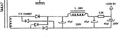
I'm trying to design a PSU for a phono/line preamp I am building. The original schematic calls for a transformer with a 190V secondary, bridge rectified and CLCRC filtered (I have attached the schematic below), to give HT 250V DC.
As it is next to impossible to find transformers with a 190V secondary, unless you make them to order, and conversely, 250V ones are extremely easy to get for next to nothing on ebay, I did just that. I have since then been playing around with PSU Designer II to try and figure out what to tweak.
At this stage, I was wondering if anyone has any idea on how I can figure out what resistive load to add to the simulation. So far, I've used the default 5k load the program starts with.
I have a few other questions, but let's first make sure I get this right.
Thank you,
Nikos
Attachments
Easier to do would to actually tell it how big the load is. For instance let's assume 8mA in total.At this stage, I was wondering if anyone has any idea on how I can figure out what resistive load to add to the simulation.
Go to the last resistor in the simulator (move over it with the mouse until the whole whitespace is highlighted not just the resistor.....)
Then right click and change....to constant current. Click Ok.
Right click again when the constant current thingy is highlighted and enter for value 1 the value 8mA.
You have now added a representative load to your circuit.
Easier to do would to actually tell it how big the load is. For instance let's assume 8mA in total.
Thanks for this, but why 8mA? How do I find out what current my pre-amp will draw to plug into the program? In theory, the article I have taken this from says that it draws 10mA, but will this not vary according to the power supply itself?
Last edited:
For example, I just ran a couple of simulations using the same circuit and a 5k resistive load, but using
a. 190V - 0.025A
b. 250V - 0.2A
secondary trafos and got .027A for (a) and a little over .04 for (b)
Would I therefore not be wrong assuming the current draw is fixed and take it from there?
a. 190V - 0.025A
b. 250V - 0.2A
secondary trafos and got .027A for (a) and a little over .04 for (b)
Would I therefore not be wrong assuming the current draw is fixed and take it from there?
Bas' advice is quite good, just set the current source to the article's stated 10mA and design your supply - it is not too critical and once everything is actually built you can then tweak the resistor value(s) slightly to get the voltage spot on. In most cases it is not that critical - a few % one way or the other should not make a significant difference.
...
At this stage, I was wondering if anyone has any idea on how I can figure out what resistive load to add to the simulation. So far, I've used the default 5k load the program starts with.
First off you don't need to care a lot about the exact plate voltage. Higher is better up to a point. Your preamp will have better headroom with more voltage. Have to looked at the load line?
The Hammond's 269esx transformer is a 190V and sells for about $40. There is an international version of it too.
With so much extra voltage to kill why not do something more creative? The first thing that comes to mind is to add another RC stage to the filter. You gain another few dB in ripple rejection at a cost of about $4. You could also add a low value 10R resistor between the diodes and first cap to limit in-rush. I notice there is no "bleeder" resistor in the power supply. You _really_ do need one simply to make the amp safe to work on and it could drop a few volts for you. The idea here is to not just burn the voltage up without putting all that the heat to good use. You could do all three: another RC stage, in-rash limiter and bleeder.
If you think about it, a bleeder resistor across the first cap and the inrush resistor toget form a volag devider. A very large in-rush and very small bleeder gives you a voltage drop and a "soft on" feature.
But really, think agin what voltage you need on the tubes the 7AX types can go 300V easy
But still you'd need to pick a value for the last resistor. You best option is to build the amp and measure it. You really can't know in advance because you can't know in advance how the tolerances of all the components will add up.
The nest thing I can think of is regulating the B+ supply. This is more complex but nothing eles you can do would improve it more.
Last edited:
Thanks for the suggestions.
OK, now onto the next couple questions:
1. Am I right in thinking that the voltage across the load will be the "max" in PSU Designer?
2. Does a value of a little over 210 sound right, given a theoretical "no load" 250v B+ DC supply?
3. Am I right in thinking I should be aiming to tweak values to get the same voltage across the load?
4. What power dissipation resistors would you suggest using?
Thanks!
4. What power dissipation resistors would you suggest using?
You could work it out by multipying the voltage drop across the resistor by the current through to get watts but you want these to run cool. Resistors create "hiss" because they are hot and will be quieter if they run cool. It is a minor point but seeing as this is a preamp you want it dead quiet.
Wire wound are the quietest type second is metal oxide. Buy them 4X larger than calculation shows and they will run cool enough. The normal advice is 2X larger than calculation. Never run them at their calculated maximum. or you will find them running at something like 80C or whatever. So do the 4X safety factor then round up to the next size.
Example, 10V drop at 10ma current is 0.1W times 4 is 0.4W so a 1/2W would do. Then I look at my supplier's web site and notice 1/2W cost $0.55 per five and 1W are $0.60 per five. For the extra penny I simply buy all 1W resistors. You can afford to overkill nickel and dime parts
You may use VR-75 and VR-150 (OR SG2S and SG3S) tubes in series instead of a bleeding resistor. Such a way you would get well regulated 225V voltage with very low ripples.
And you are getting cool looking power presence indicators for free...
And you are getting cool looking power presence indicators for free...
Thanks for the suggestions.
OK, now onto the next couple questions:
1. Am I right in thinking that the voltage across the load will be the "max" in PSU Designer?
2. Does a value of a little over 210 sound right, given a theoretical "no load" 250v B+ DC supply?
3. Am I right in thinking I should be aiming to tweak values to get the same voltage across the load?
4. What power dissipation resistors would you suggest using?
Thanks!
The voltage across the load will be max when the tubes are not conducting. With SS diodes, the voltage can rise to sqrt2 X transformer secondary when the tubes are cold.
If you change the load to 0 ma, you should see the max voltage.
Once you've got the load changed to constant current from resistive per Bas' comments above, click on the ma load box (not larger yellow box you clicked on to change from resistive to current, the smaller yellow box of the current load) click the "stepped load" box and put in a second current greater or less than the nominal current to see what voltages you'll end up with. You should do this after 5 seconds or so since you want to change the load when the voltage has settled out (not while it's still rising). Most important for this exercise is to check for ringing/overshoot in the voltage when the current changes. You don't want any overshoot, ie you want the circuit to be overdamped.
Use ohm's law to calculate resistor power ratings, and pick resistors that exceed the power dissipated by a fair bit, like double. They'll run cooler and quiter as already mentioned. You can easily get voltages across the resistors right out of PSUDII.
Since you are using bridge rectification, the diodes need to have a voltage rating at least sqrt2 X transformer secondary as well. It's also a good idea to use fast recovery diodes instead of the plain vanilla ones shown is the schema, ie UF4007 instead of 1N4007. Snubbing each diode with a 10 nf 2kv ceramic cap also helps keep diode switching noise down. Connect the caps in parallel with each diode.
Last edited:
If you have voltage "to kill" then why use a CLC input filter? Using an LCRC will be a lot easier on your transformer and rectifier and first capacitor enabling a lot longer life expectancy. imho.
AM
AM
Once again thanks to everyone - I know I am repeating myself but this is very interesting and useful stuff!
I am now split between AmadeusMozart's suggestion of LCRC and ChrisA's of RCLCRC. What are the advantages of the two?
I am now split between AmadeusMozart's suggestion of LCRC and ChrisA's of RCLCRC. What are the advantages of the two?
Once again thanks to everyone - I know I am repeating myself but this is very interesting and useful stuff!
I am now split between AmadeusMozart's suggestion of LCRC and ChrisA's of RCLCRC. What are the advantages of the two?
With an LCRC (choke input) PS filter you end up with a max B+ voltage of about 90% or your transformer secondary voltage; it also a very smooth current waveform and a few other advantages that escape me at the moment. One caveat with a choke input, you need to have a minimum current draw all the time or it starts to act like a cap input filter with a B+ of sqrt2 x transformer secondary voltage. Sizing the bleeder resistors can sometimes do double duty to provide the minimum current.
The RCLCRC is a 3 stage filter for reducing voltage ripple if you've got volts to spare. The one downside to this is that all that R is increasing output resistance of the PS and turning power into heat. One advantage here is that R's a way cheaper than L's so it's a economical way to smooth the waveform.
Another way to reduce/adjust the output voltage without wasting power as heat is to use a CLC filter where the first cap is small and is adjusted to give the desired B+ voltage. Typically C1 values ranging from less than 1uf to about 10uf are effective in changing the B+.
You can check this out with your existing model by reducing the values of C1 below 10uf. One way to think about this is as a B+ continuum from a choke input filter to a cap input filter; really small values of C1 (less than 1uf) are almost like no cap at all (choke input) and your B+ voltage can be as low as .9 x transformer secondary and C1 values above 10uf or so are way into the cap input filter range at sqrt2 x transformer secondary.
For added safety, put a bleeder R across the caps on both sides of the choke. That way, if you working on the PS and disconnect the choke both caps will still bleed down. This was a suggestion from Tubelab George a while back that makes sense to me. Anything from 200K/3W to 560K/3W or so would be fine. Larger value bleeder R's waste less power when using the amp but take longer for the voltage to bleed down when the amp is off.
Last edited:
quick question:
I have some bridge rectifiers (all in one) lying around, can I use them instead of the four diodes in the bridge? The factsheet for the component is this one:
http://docs-europe.origin.electrocomponents.com/webdocs/0dcf/0900766b80dcfb02.pdf
and it's the GBL10 (4A - 1kV) variant I have.
thx,
Nikos
I have some bridge rectifiers (all in one) lying around, can I use them instead of the four diodes in the bridge? The factsheet for the component is this one:
http://docs-europe.origin.electrocomponents.com/webdocs/0dcf/0900766b80dcfb02.pdf
and it's the GBL10 (4A - 1kV) variant I have.
thx,
Nikos
btw, almost there now, tubes have arrived and everything bar the PSU is ready, should be up and running by weekend 🙂
quick question:
I have some bridge rectifiers (all in one) lying around, can I use them instead of the four diodes in the bridge? The factsheet for the component is this one:
http://docs-europe.origin.electrocomponents.com/webdocs/0dcf/0900766b80dcfb02.pdf
and it's the GBL10 (4A - 1kV) variant I have.
Yes, for B+ rectifier.
Thanks for the suggestions.
OK, now onto the next couple questions:
1. Am I right in thinking that the voltage across the load will be the "max" in PSU Designer?
4. What power dissipation resistors would you suggest using?
Thanks!
#1 "RMS is more informative. however use "max" when spec'ing parts.
#4 Look at the voltage drop across each, you can use ohm's law to find the drop. Then multiply current times volts to get watts. In theory is this works out to (say) 0.7W you could use the next highest rated resistor a 1W. But if you do it will run hot. Near it's maximum temperature. So as a rule of thumb use a resister that is rates for at least twice the required power and even 4X is better. At 4X they are just a little warm at 1X (right at the limit) they will burn your finger. But there is not way out of the requirement to actually do the math for each resistor, unless the designer has done this for you.
BTW a power suppply is a very good place to use wire wound resistors. Maybe even use oversized ones just so you can get the WW type.
If you have voltage "to kill" then why use a CLC input filter? Using an LCRC will be a lot easier on your transformer and rectifier and first capacitor enabling a lot longer life expectancy. imho.
AM
I agree you get lower DC voltage from LCRC. But the LCRC filter is harder to design. They can, if designed wrong do nasty things like gyrate wildly if there is no load or on start up. No offence, but if the OP has to ask these kinds of questions he may have trouble with a choke input filter. Resisters kind of automatically supply dampping. I auggested adding more RC stages to kill the voltage because I though he'd have the best chance of getting that to work not because if reduces heat
I think this is a low power amp and even if the voltage is "burned up" in resistors it will not be much. It is not like he is building a 1KVA supply.
- Status
- Not open for further replies.
- Home
- Amplifiers
- Tubes / Valves
- PSU ignorant