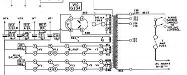
I have a transformer from an old heathkit s99, I presume it is approx 200ma but I'm not sure. I've attached a schematic for the circuit it came from. It was powering 4ecl86 and 3 ecc83's and 2 ef86's.
I have no idea of what values to enter into duncans psu designer, is the RMS V = 270 x 1.414 = 381V - and then how do I calculate the source resistance?
Is there a way to calculate more info from this transformer seeing as on the full scematic
HT 1 = 320V
HT 2 = 270V
HT 3 = 250V
cheers Stuart
I have no idea of what values to enter into duncans psu designer, is the RMS V = 270 x 1.414 = 381V - and then how do I calculate the source resistance?
Is there a way to calculate more info from this transformer seeing as on the full scematic
HT 1 = 320V
HT 2 = 270V
HT 3 = 250V
cheers Stuart
Attachments
"I have no idea of what values to enter into duncans psu designer, is the RMS V = 270 x 1.414 = 381V - and then how do I calculate the source resistance?"
look at the data sheet for V10: GZ34
http://www.wooaudio.com/docs/tube_data/5AR4.pdf
Hope that helps.
look at the data sheet for V10: GZ34
http://www.wooaudio.com/docs/tube_data/5AR4.pdf
Hope that helps.
RMS voltage is 270V. Peak will be 381V. I believe PSUD2 uses RMS, so enter 270V. For source resistance measure primary and secondary resistance with a DVM, and then enter the results into the PSUD2 transformer calculator (or do the calculation yourself).
Thanks Df96, I didn't realise I could just stick a DVM on primary winding (mains side?) and then over the secondary winding (leave CT out?) to get resistances - that I could then apply to a formula to find the source resistance!
If I then setup a circuit in PSUD2, using full wave rectifier (GZ34) followed by CRCRC will I be able to identify the current throught the circuit by seeing what flows through the final 5K resistor that PSUD2 puts in by default?
Or do I change that final 'resistor to ground' to a resistance that matchs the perceived resistance of the amp I wish to build?
If I wish to build the original Baby Huey amp that gingertubes modded for UL operation, should I be changing the value of the final 5k resistor of PSUD2?
Thanks again for everyones help here, and thanks Dug for the data sheet
I'm not sure about the CT, as I can't remember what PSUD2 assumes for secondary resistance.
You can use either a resistor or constant current load for your PSU. A resistor may better approximate the load of a real valve amplifier. Set it to whatever value is appropriate.
You can use either a resistor or constant current load for your PSU. A resistor may better approximate the load of a real valve amplifier. Set it to whatever value is appropriate.
Thanks DF, but how do I know what value is appropriate for the final R in PSUD2
and... I just read somewhere that the primary resistance is taken across the mains, and the secondary is HALF the secondary... I'm guessing this means CT to one side of the secondary?
and... I just read somewhere that the primary resistance is taken across the mains, and the secondary is HALF the secondary... I'm guessing this means CT to one side of the secondary?
Would it be safe to say that the current drawn by this circuit (4 x ecl86) will be 4 x 35mA which is 140mA?
That may be a reasonable estimate. You can calculate quiescent current by using Ohm's Law on the cathode resistors. A typical push-pull Class A output will increase its current draw by 10-20% at full output, but that will only be on music peaks so can almost be ignored. Class B will increase more, of course.
A design should say what current it draws. The designer must know, because it is part of the design process.
A design should say what current it draws. The designer must know, because it is part of the design process.
with PSUD2, instead of an end resistor, you can use a constant current load. It's much handier than a final resistor - especially if you really do know what the "average" mA will be. Obviously easier with a Class A circuit.
Great guys thanks...
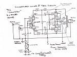
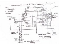
So for the circuit posted below I can assume that V across the cathode of final stage is 10.5 V and the cathode R is 390ohms...
Therefore I = 10.5 / 390 = 0.0269 or 27mA
This is the idle current which would be the same as the quiessent current seeing as this amp operates mainly in class A (is this correct?)
and.... I,m still trying to figure out how the first stage only draws around 1mA and has a constant current source to determine this...
my limited background in physics always taught me that the current was the same for the entire circuit?
Attachments

Source resistance calculated 1
Ok, thanks to all here - I'm making headway!
primary resistance = 9ohms
secondary resistance = 63ohms (CT to Sec)
Source resistance = (primary resistance / (Vpri/Vsec)2) + Secondary resistance
Vpri = 230
Vsec = 270
(Vpri/Vsec)2 = 0.726
therefore Source resistance = 75.3ohms
Ok, thanks to all here - I'm making headway!
primary resistance = 9ohms
secondary resistance = 63ohms (CT to Sec)
Source resistance = (primary resistance / (Vpri/Vsec)2) + Secondary resistance
Vpri = 230
Vsec = 270
(Vpri/Vsec)2 = 0.726
therefore Source resistance = 75.3ohms
- Status
- Not open for further replies.
- Home
- Amplifiers
- Tubes / Valves
- PSU id and help (psu designer ii)