Greetings all,
I've just finished assembling my 41Hz Amp3, and now I'm trying to decide how to power it. From all of threads I've pored through, it looks like the options are a 12v SLA battery with some input caps, or a 12-14.6v linear/switching regulated PSU.
The battery option seems simple enough, and supposedly it can last for several days of continuous use before it needs recharging. But that raises the issue; am I going to have to tear down my amp once a week to charge it? ..or are you guys installing some sort of a concurrent or switchable recharging circuit in parallel with the battery?
On the other hand, I feel pretty lost over all the regulated PSU's out there. I know this is the DIY forum, but building one from scratch seems a little intimidating to me. Are there any specific commercially-available PSU's that really unleash the full potential of the Amp3? What are you guys using?
I'm sorry if this has all been discussed at length before, but I've spent the last two weeks just reading through thread after thread and haven't found a clear consensus on what works best. I'd really appreciate some guidance. Thanks!
-Mike
michaelconnor said:I've spent the last two weeks just reading through thread after thread and haven't found a clear consensus on what works best.
That's because there isn't one!
")
Go get one of these, they work really well. There are improvments you can make, but it will get you started down the right path.
BG Micro supply
Re: Re: PSU for Tripath Amp3, where to start?
Thanks! I was beginning to suspect that is the case.
Are there any other components I should throw into the power line? There are (what appears to be) two radial input caps already integrated into the Amp3 board, so I shouldn't have to add any additional caps right? I just want to make sure I've covered all the bases.
panomaniac said:
That's because there isn't one!
Thanks! I was beginning to suspect that is the case.
Are there any other components I should throw into the power line? There are (what appears to be) two radial input caps already integrated into the Amp3 board, so I shouldn't have to add any additional caps right? I just want to make sure I've covered all the bases.
For my amp3 I had a big improvement in the dynamics when I added a 1,000uF Panasonic FM capacitor with a parallel snubber (0.47uF polystyrene in series with 0.5 ohms) on the power supply input on the AMP3. As the quality of the power supply is important for Class D amps, this combination allows you to use a cheaper power source and still get a decent sound.
Its important that you mount these components close to the amp3 board.
You could also change the power supply decoupling caps on the amp3 board to better ones.
Regards,
Dean
Its important that you mount these components close to the amp3 board.
You could also change the power supply decoupling caps on the amp3 board to better ones.
Regards,
Dean
michaelconnor said:Greetings all,
The battery option seems simple enough, and supposedly it can last for several days of continuous use before it needs recharging. But that raises the issue; am I going to have to tear down my amp once a week to charge it? ..or are you guys installing some sort of a concurrent or switchable recharging circuit in parallel with the battery?
-Mike
Hi Mike,
I wired a charger to the case via a panel mount jack. Wire it internally to switch the battery between either the amp or the charger. If the amp is not on then the battery is charging. Here is a link to Batterymart.com which has good deals on sealed lead-acid (SLA) batteries.
http://www.batterymart.com/battery.mv?p=SLA-12V2-3
They usually have an appropriate charger listed at the bottom of each page. Don't forget to buy a cable with the charger. You can go as low as 1.3AH but 2 to 3AH is a nice size for a small case and still have good staying power. I have been running a tweaked SI T-Amp and a Scott Nixon DAC from SLAs for about a year and it works very well.
Having said all of this I just bought a 10A 12volt SMPS power supply from EBAY to see how that compares. Some folks feel that it sounds even better than batteries.
Half the fun is in trying different things out...
Good luck,
Paul
Cool. I'll have to try that out.
What you're describing should look something like below, right?
......Vs ---|------------|---------------Vin
...............|................C (0.47uF)
...............C (1kuF)......|
...............|................R (0.5ohm)
...............|................|
....GND----|------------|--------------GND
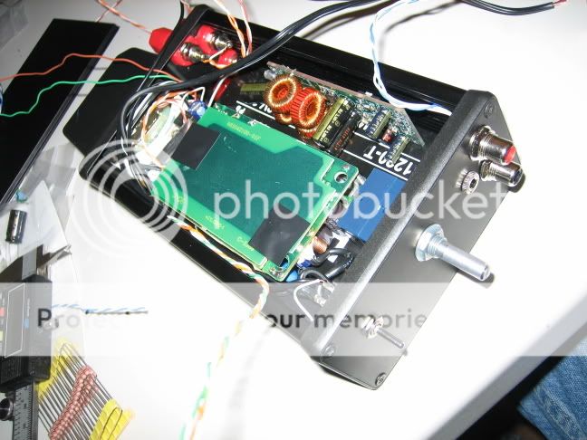
Okay, this should be fun. Since I despise wall-warts, I'm going to try and fit the DVE PSU, this battery and a charger into a hammond case. This way, I can experiment with sources, have portability, or use the PSU while the battery is charging. I'll have to post some pics when I get everything assembled.
I did the layout right on my desk because I'm feeling impulsive
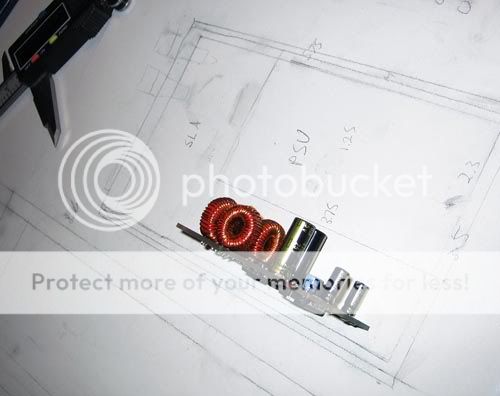
It looks like some components will have to get a little comfortable, but we shall see...
I did the layout right on my desk because I'm feeling impulsive
It looks like some components will have to get a little comfortable, but we shall see...
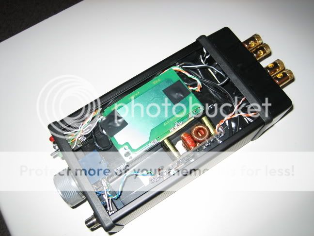
Getting there...
Well, I've started assembly, but I'm still waiting on a few parts, namely the AC supply. So far, the only problem I've encountered is that I've underestimated how much space would be needed to fit everything. To resolve this, I ghetto-rigged a wall-wart case to fit the lead-acid recharging transformer. It's all not quite what I was going for, and perhaps I was a little ambitious with the integration, but i suppose this is my first audio-amp build.
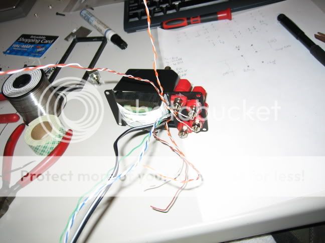
Well, I've started assembly, but I'm still waiting on a few parts, namely the AC supply. So far, the only problem I've encountered is that I've underestimated how much space would be needed to fit everything. To resolve this, I ghetto-rigged a wall-wart case to fit the lead-acid recharging transformer. It's all not quite what I was going for, and perhaps I was a little ambitious with the integration, but i suppose this is my first audio-amp build.


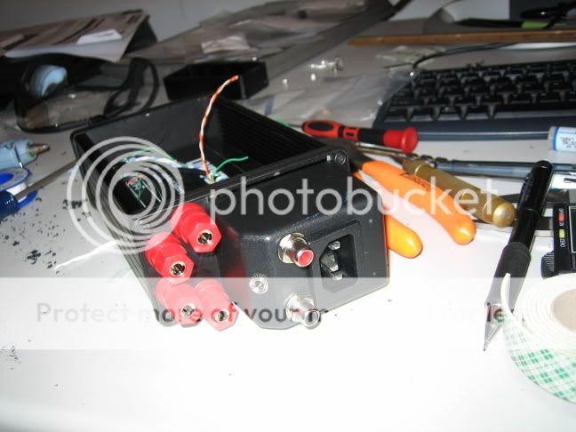
Sorry but to me that whole setup with the signal cable entering right next to a mains socket, then internally passing right next to a transformer is just wrong. I have also build and AMP 3 into the same chasis as that but i end up putting the power source into a seperate box.
IHMO keeping mains AC volatge as far from signal cables and PCBs can only be a good thing.
Phil
IHMO keeping mains AC volatge as far from signal cables and PCBs can only be a good thing.
Phil
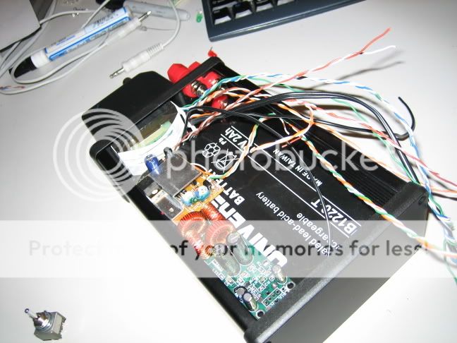
That should work much better. Keeps the input away from the AC. You still have the AC and x-former very near your speaker lines. Be careful there. Maybe a dividing wall of plastic and metal there? Plastic side toward the x-former, of course.
Speaker lines don't often pick up noise, but those are very close to a radiating source. You'll need to be extra careful about 120V accidentally getting onto the speaker wires, too. Could be rather "shocking" if not down right deadly.
Be careful
Speaker lines don't often pick up noise, but those are very close to a radiating source. You'll need to be extra careful about 120V accidentally getting onto the speaker wires, too. Could be rather "shocking" if not down right deadly.
Be careful
panomaniac,
Right now I've got the amp sitting in an insulated steel tray that's grounded to the amp itself. I'd imagine this will make a slightly better ground plane against noise from the nearby power supplies.
Another question; I'm trying to decide what all to ground to the main chassis. I have the mains ground wire, the battery (-) wire, the AC PSU (-) wire, and signal input ground (already on faceplate). I know one should try to keep the power grounding nodes separate from the signal nodes, but I've already noticed some static build-up in the chassis while testing the PSU's, and I'd just like to tie everything to one reference point. Would this be a mistake?
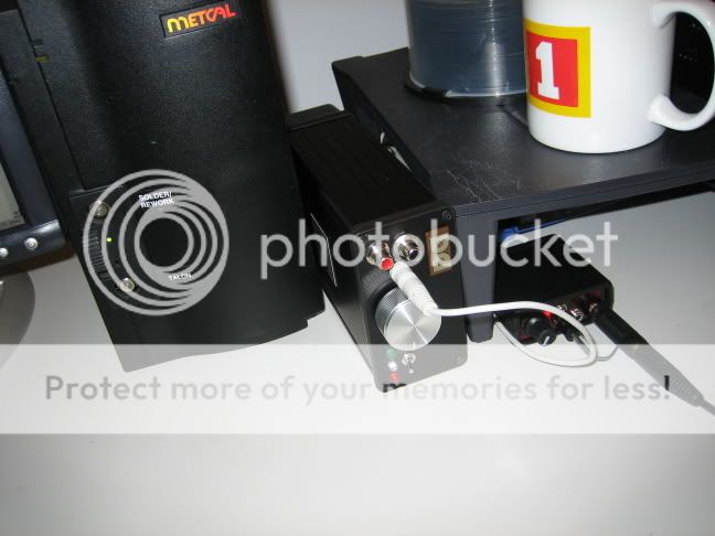
Update: Finished my first amp!
I eventually gave up on fitting in the battery charger and rebuilt the back of the enclosure. I've also threw on some Dolby and Dell logos for vain aesthetics.
I'm using the 1mF Cap/snubber on the input, and the PSU from BGMicro seems to be working out. I'm using some Large Advent loudspeakers, which aren't exactly efficient, and the volume becomes uncomfortable at only 2/3's turn on the 50k Alps pot. The resolution and dynamics have really surprised me. I suppose this is what all the hype is about, right? The high end is slightly harsh right now, but I understand this should disappear after a few dozen hours?
Anyway, thanks to all for the input! This has been a fun experience.
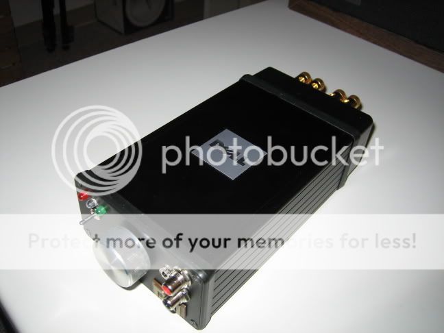
Hey! Looks nice, very nice indeed. Good job.
As for the volume, when you get past 2/3, or about 1 o'clock, you are probably running into clipping which will sound bad, and loud. Just keep it under that point and enjoy the music.
Oh yeah, it will smooth out with time. Have fun!
As for the volume, when you get past 2/3, or about 1 o'clock, you are probably running into clipping which will sound bad, and loud. Just keep it under that point and enjoy the music.
Oh yeah, it will smooth out with time. Have fun!
- Status
- This old topic is closed. If you want to reopen this topic, contact a moderator using the "Report Post" button.
- Home
- Amplifiers
- Class D
- PSU for Tripath Amp3, where to start?