1 s is too long. It takes only a few cycles to pass the inrush current, usually 60 to 100 ms.akis said:Here is the schematic for powering from mains, please tell me what you think
You should always put a flyback diode or R-C network across a relay coil.
I am not sure about graphical symbols in the UK. You need a NO contact or make contact. In most places, what you drew would be interpreted as NC or break contact.
If you use a relay with a higher coil voltage you will waste less energy in the series resistors. Even better would be a dedicated power supply for the soft-start circuit.
http://sound.westhost.com/project39.htmtinitus said:Would surely be nice if someone would design a good working softstart
Inrush current is a inherent characteristic of toroidal transformers.
It has nothing to do with the resistance of the primary or capacitors hanging on the secondary. E cores transformers do not suffer from inrush current.
Inrush current in toroidal transformers are due to the memory it holds at switch off. You can read all about core memory from some 30 - 40 years ago.
If you don't want to a use complex circuit to control the "inrush" current the simplest method is using an NTC in series with the transformer.
The NTC will start cold at a few ohms that limit the start current and end up hot at a few Milli-Ohm within a short time.
Remember an NTC runs hot, do not mount it next to wiring that can melt.
If you decide to make a soft start using a relay, be sure to use one with contact rating for the voltage that you will use.
A soft start circuit consist of a simple timer driving a relay with normally open contact and power resistor or NTC mounted across the contact. The timer closes the relay contact a second or so after you turn power on. The timer must reset after power is turned off.
Yes, they do. They suffer from the same memory effect, only at a lower level of remanence flux, hence produce a smaller inrush current than toroids. Still an EI core transformer without soft-start needs a 2-3 times bigger primary fuse than its nominal current.Nico Ras said:E cores transformers do not suffer from inrush current.
Please ignore my circuit above, it is completely wrong, awful.
I just experimented (with smaller voltages of course) and the idea will not work. A potentiometer, or a carefully selected single voltage drop resistor across the VAC input will work, but for small voltages. I would not dare use it across the mains.
The potentiometer means we will need to draw a lot of power and use some 30 Watt resistors, whereas the single resistor requires less power but is also dependent on the consumption of the circuit. Which varies.
And if the circuit for some reason does not consume the calculated current, then the filter cap (C1) will develop the full input voltage across its terminals, and probably destroy the circuit and maybe set the house on fire.
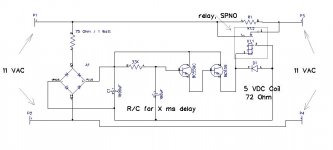
Anyway, here is the circuit, almost exactly as I tested it a minute ago. It all hinges on the coil to be functioning perfectly. And on startup, while time delay R/C is charging, C1 receives almost the full input voltage... So that idea would not work with 240 Volt mains.
But we could replace the 75 R resistor with a small transformer, those miniature ones and then it could be used across the mains.
I just experimented (with smaller voltages of course) and the idea will not work. A potentiometer, or a carefully selected single voltage drop resistor across the VAC input will work, but for small voltages. I would not dare use it across the mains.
The potentiometer means we will need to draw a lot of power and use some 30 Watt resistors, whereas the single resistor requires less power but is also dependent on the consumption of the circuit. Which varies.
And if the circuit for some reason does not consume the calculated current, then the filter cap (C1) will develop the full input voltage across its terminals, and probably destroy the circuit and maybe set the house on fire.
Anyway, here is the circuit, almost exactly as I tested it a minute ago. It all hinges on the coil to be functioning perfectly. And on startup, while time delay R/C is charging, C1 receives almost the full input voltage... So that idea would not work with 240 Volt mains.
But we could replace the 75 R resistor with a small transformer, those miniature ones and then it could be used across the mains.
Attachments
You aren't far off. There is a way to do this kind of circuit, using the reactance of an X2 rated capacitor to drop the mains supply. I remember Elektor printed such a circuit once with one of their amplifiers - no doubt you will find it somewhere on the web!
Personally I wouldn't risk it. Get a really small 9VAC transformer and use that.
edit: Found it here - http://mitglied.lycos.de/Promitheus/delay_circuit_for_toroids.htm
edit 2: I wondered how small a transformer you can get, and how easy they are to get. Seems you can get 0.35VA and 0.5VA easily from Rapid:
http://www.rapidonline.com/netalogue/specs/88-3574.pdf
For a "standby" supply in an amp I made, I used a 9-0-9 250mA transformer that I got from an old beside clock/radio. It's small and has enough current to power a microcontroller and a few relays")
Personally I wouldn't risk it. Get a really small 9VAC transformer and use that.
edit: Found it here - http://mitglied.lycos.de/Promitheus/delay_circuit_for_toroids.htm
edit 2: I wondered how small a transformer you can get, and how easy they are to get. Seems you can get 0.35VA and 0.5VA easily from Rapid:
http://www.rapidonline.com/netalogue/specs/88-3574.pdf
For a "standby" supply in an amp I made, I used a 9-0-9 250mA transformer that I got from an old beside clock/radio. It's small and has enough current to power a microcontroller and a few relays
Good stuff. I was thinking a small/tiny transformer was the way to go, avoiding completely the need for high voltages and high voltage components/tracks. I was thinking of a power on/off switch using this low DC to activate a relay at the back end of the unit, all away from the front where all the other pots and switches and jacks are, and where you can/will spill your cup of tea/beer (guitar amp).
So I was thinking of building such a little board that would do the remote switching and additionally provide +-12 V DC at 1A max, for whoever needs.
So I was thinking of building such a little board that would do the remote switching and additionally provide +-12 V DC at 1A max, for whoever needs.
can be made to work.akis said:
1. Power the relay from rectified mains
2. Power the relay from the rectified output of the transformer
Here is the schematic for powering from mains, please tell me what you think
But they rely on power/voltage from the main transformer. If the voltage is slow to build up or low for some reason the relay may not pull in and the resistor then overheats.
Far better to use a real timing circuit (555 are cheap) that is powered from a separate transformer.
There are too many mistakes in this post.Nico Ras said:Inrush current is a inherent characteristic of toroidal transformers.
It has nothing to do with the resistance of the primary or capacitors hanging on the secondary. E cores transformers do not suffer from inrush current.
Inrush current in toroidal transformers are due to the memory it holds at switch off. You can read all about core memory from some 30 - 40 years ago.
If you don't want to a use complex circuit to control the "inrush" current the simplest method is using an NTC in series with the transformer.
The NTC will start cold at a few ohms that limit the start current and end up hot at a few Milli-Ohm within a short time.
Remember an NTC runs hot, do not mount it next to wiring that can melt.
If you decide to make a soft start using a relay, be sure to use one with contact rating for the voltage that you will use.
A soft start circuit consist of a simple timer driving a relay with normally open contact and power resistor or NTC mounted across the contact. The timer closes the relay contact a second or so after you turn power on. The timer must reset after power is turned off.
Better to just ignore all the content.
AndrewT said:There are too many mistakes in this post.
Better to just ignore all the content.
Why do you say this. Do you know much about the subject. Our company has designed and manufactured several millions transformers since 1961.
The diode is the right way round, because it is a fly-back diode. Its purpose is to protect other components, including transistors, from the spikes a relay coil produces, when it is deenergized.Nico Ras said:You are going to destroy the transistors, the diode is wrong way round.
Quasi offers a soft start circuit for his [relatively large] amp projects. It just leverages the time constant of a capacitor for the delay. And it uses a separate small power transformer for its own supply.
Quasi's project website
Look down the menu, you'll see his soft start circuit.
..Todd
Quasi's project website
Look down the menu, you'll see his soft start circuit.
..Todd
Hi Nico,
It seems to me, based on your description of the NTC thermistor, that one disadvantage to this would be that once the amp has been running and the NTC warmed up, cycling the mains power (accidental or otherwise) at that point would allow full inrush current to the transformer. No?
..Todd
It seems to me, based on your description of the NTC thermistor, that one disadvantage to this would be that once the amp has been running and the NTC warmed up, cycling the mains power (accidental or otherwise) at that point would allow full inrush current to the transformer. No?
..Todd
- Status
- This old topic is closed. If you want to reopen this topic, contact a moderator using the "Report Post" button.
- Home
- Amplifiers
- Solid State
- PSU for power amp