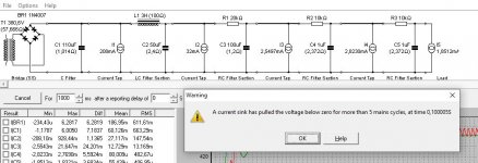
When using PSUDII I often get the warning message:
"A current sink has pulled the voltage below zero for more than 5 cycles, at time ..."
I understand that tubes are not a constant current sink on startup, but what when they are already hot and you turn them off and on again in a quick succession ( hot start), would this pull the voltage below zero and what effect would this have?
There must be a reason why the designer of PSUDII added the warning.
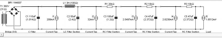
When entering known working designs of amps, as in the attachment, I do get the message which is odd to me.
"A current sink has pulled the voltage below zero for more than 5 cycles, at time ..."
I understand that tubes are not a constant current sink on startup, but what when they are already hot and you turn them off and on again in a quick succession ( hot start), would this pull the voltage below zero and what effect would this have?
There must be a reason why the designer of PSUDII added the warning.
When entering known working designs of amps, as in the attachment, I do get the message which is odd to me.
Attachments
Highly likely an initial condition and convergence aspect. Current sinks force a set condition no matter what, and inductors want a constant current. If the sim continues and provides acceptable steady-state results then I wouldn't worry about the warning at all. The only way to avoid all that is to move to LTSpice and set up initial conditions.
If your concern is about the dynamic conditions leading up to steady-state, then you likely need to just use a simpler model with a resistive load, or fewer current sinks.
Component values are never 'that exact', so I'd caution about not getting hung up on using a value whose precision far exceeds any practical output - it may lead to a false sense of appreciation of what the sim is telling you.
Simulating a cold or hot start is a separate effort than simulating steady-state. All you can really do is use cold-start or 'hot-start' parameter values in separate sims, and just limit your concern to the time region of issue.
For a cold start, there won't be load currents, so you could remove all current sources - which is one advantage of putting a B+ bleed resistor on the end (as it can be simulated). If you have an NTC on the primary, then it's cold resistance gets included in the transformer winding resistance calculator.
For a hot-start, the loads are all in place, but even then there is some approximation as to how each stage biases itself as B+ rises, as coupling cap time-constants and output transformer primary inductance time-constants all can influence the first few hundred milliseconds.
And some components are non-linear for starters, such as the inductance of a choke. So any outcome plot has to taken with caution.
Last edited:
There are no real-world "current sinks". (Not impossible, but almost never worthwhile.)
When the math goes crazy, use RESISTOR. 530V at 208mA is 2,558 Ohms. This won't try to "go below zero".
WHY are I3 I4 I5 about 2 AMPS?? After 10k-20k resistors? A real "current sink" would be stuck at zero. A "true" current sink certainly "should" go the other way. By about 139,470 Volts.
When the math goes crazy, use RESISTOR. 530V at 208mA is 2,558 Ohms. This won't try to "go below zero".
WHY are I3 I4 I5 about 2 AMPS?? After 10k-20k resistors? A real "current sink" would be stuck at zero. A "true" current sink certainly "should" go the other way. By about 139,470 Volts.
comma is decimal point, so I3 is 2.5mA, although the OP has somehow used a calculator to get a mA value to 4 decimal places.
Thank you all for your answers. Lol yes I used four decimals for extra accuracy 😉 My PSUD wants me to use comma's as decimal points. Also some capacitors are the wrong value in the PSUD screenshot that I showed, I use the one shown now.
I have since modeled the whole amp in LtSpice, except the transformers and rectifier. I used tube models with the transient analysis. I started the external DC voltages at 0V.
Is this the correct way to simulate this?
V(C5) stays below zero for 8.5mS
V(C4) stays below zero for 6mS
V(C3) stays below zero for 0.75mS
This is all far below the over 5 mains cycles ( 100mS) that PSUDII simulates.
What I still fail to understand is what is the problem with going below zero is anyway. All voltages come up to the desired ones eventually.
Does anyone have any insight on this?
Attachments
> My PSUD wants me to use comma's as decimal points.
I was being a stupid American. Obviously PSUD asks the operating system for "locale" which gives format for dates and numbers the user ('s language) prefers.
Many seconds of "below zero" (reverse voltage) would heat-up electrolytic caps. However this is surely an artifact of simplified calculation. While some doublers really will go "the wrong way" for a few cycles at start-up, your plan is just an Ideal Current SOURCE pulling power out of thin air; won't happen in real life.
- Home
- Live Sound
- Instruments and Amps
- PSU Designer II Warning Message