Hello, trying for over a year to put a M2X amplifier together. Finally parts came available placed all orders after frustrating time tracking down parts from all over the globe. Yes I made errors , I asked for a 400va,18-0-18 trans expecting two sets of wires. Well only one set for 117v ,one wire for shield,and three for secondary. Two red and a grey, the center tap i assume. I have the psu boards from store here and all ready for power. I have the dim bulb tester also but i need more info I need a schematic or a drawing how to hook up, can only get one side at a time to work with two rectifiers. I am assuming its not possible that way?I have the bridge rec's .Help would be appreciated so i can catch the bug big time. Next time i'll get the transformer with all the wires i see in all the builds .
A 3-wire center-tapped secondary is actually pretty common -- not sure what builds you've been looking at.
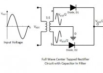
If you were you planning a dual-bridge rectifier supply, that won't be possible with the 3-wire secondary. Perhaps that's some of the confusion.
The transformer you have would have been considered 'perfect' before the wave of dual-bridge lust that has now swept the Diy mindset. And its something that makes very little sense to me: Twice the number of rectifiers, twice the voltage loss, twice the waste heat to dissipate, ...
How are your bridges marked? Most I've seen in recent years have a couple of '~'s, and a '+' and a '-'. The squiggly's go to the red leads, the plus and minus become your main rails, where you'll connect your big filter caps. Then each other cap terminal connects to the gray center tap, observing correct polarity, and becomes the PSU ground.
Glad you're being smart with the bulb tester! Definitely the way to go.
Best luck,
Rick
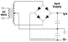
It would be helpful to post a schematic of your rectifier set-up. Then it will be obvious.
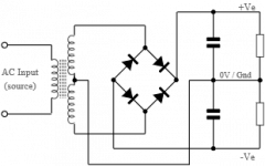
See attached. Double that up with reversed diodes and you also get a neg voltage.
Jan
See attached. Double that up with reversed diodes and you also get a neg voltage.
Jan
Attachments
Last edited:
Thank you everyone I have a working psu!🙂
I came across conflicting drawings that's why I posted, glad i did.
Now on to the amp ,few parts still in transit hope all goes well ther.
Thanks again.
I came across conflicting drawings that's why I posted, glad i did.
Now on to the amp ,few parts still in transit hope all goes well ther.
Thanks again.
- Home
- Amplifiers
- Power Supplies
- PSU center tap wiring,help!