Hi,
I'm about to start building Mikael Abdellah's KT88SE amp, and I have a question...
I have four large motor caps, Nokia 20uF/400VAC and I was wondering if that will do for the PSU. I was thinking 20uF - 10Hy - 60uF (3 x 20 parallel), but will it be enough filtering for this circuit?
I do have other options with electrolytics, but it would be nice to use these caps for something.
They look like this: http://homepage.mac.com/roffe/s0m68.jpg
If you want more filtering and rectifiers can handle it you could stick the electrolytics on the rectifier side of the chokes and have all oil caps on the amp side.
Vennelig hilsen fra London! Motor run caps are excellent for power supplies. I agree with the previous poster - use an electrolytic in first position, but not after that. I'd follow that with the choke, then a couple of motor run caps, another choke and the last motor run. I haven't modelled this, but you can do this in duncanamps PSUD. I'd certainly prefer two chokes. Maybe the two motor runs are best in the last position and one in the intermediate position. Andy
showdown said:Hi,
I'm about to start building Mikael Abdellah's KT88SE amp, and I have a question...
I have four large motor caps, Nokia 20uF/400VAC and I was wondering if that will do for the PSU. I was thinking 20uF - 10Hy - 60uF (3 x 20 parallel), but will it be enough filtering for this circuit?
I do have other options with electrolytics, but it would be nice to use these caps for something.
They look like this: http://homepage.mac.com/roffe/s0m68.jpg
I built Mikael's KT88 as a pair of monoblocks. For each I used only a 40uF, 8Hy, 100uF. That setup provides smooth B+ to a single 6N1P and a KT88. To power two KT88s I might be tempted to add a bit more capacitance.
Like the other posters have said, you can use cheaper 'lytics before the choke and stack your motor runs after it. If you are doing tube rectification though you have to be sure not to exceed the recommended capacitance of your rectifier tube. For a 5U4G (what I used) that is 40uF. That means that 40uF is the most you can have between the rectifier and the choke (or rectifier and the first resistor in a CRC).
Thanks for the replies and suggestions.
I'll try with a 40uF electrolytic in the first position and all the motor caps paralleled after the choke. 80uF isn't much, but I can probably add more capacitance if it's necessary.
-Rolf
I'll try with a 40uF electrolytic in the first position and all the motor caps paralleled after the choke. 80uF isn't much, but I can probably add more capacitance if it's necessary.
-Rolf
Is this on a stereo chassis or two mono ones?
If it's a stereo chassis, you presumably want to put 80uF (two caps) after the choke, then the other two with dropping resistors for the input section - it's quite important they use motor run caps too.
If it's two mono amps, it would be worth getting some more motor runs for the input stages. Andy
If it's a stereo chassis, you presumably want to put 80uF (two caps) after the choke, then the other two with dropping resistors for the input section - it's quite important they use motor run caps too.
If it's two mono amps, it would be worth getting some more motor runs for the input stages. Andy
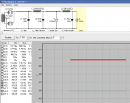
I've fiddled a bit with PSUD now, I've got an extra 10H/125mA choke that possibly could be used for the input section and a couple 40uF motor caps in addition to the 4 x 20uF.
I haven't really decided on the rectifier yet, I've got both GZ34 and 5U4G. If I'm going to use the 5U4G, I'll have to specify a higher secondary voltage for the power transformer. Decisions, decisions...
The B+ is a little bit higher than the 400V in the amp schematic, but I'm guessing that won't matter much... or will it?
If you have any suggestions, please let me know.
-Rolf
Attachments
showdown said:...
The B+ is a little bit higher than the 400V in the amp schematic, but I'm guessing that won't matter much... or will it?
If you have any suggestions, please let me know.
-Rolf
Rolf,
It sounds like you are on the right track. I used the 5U4G in my PS for this amp primarily because I like how they look! 😀
My B+ ended up at 425 which is well within 10% so in the tube world it is spot on. If your B+ comes out within 10% of target you should be fine.
That 125mA choke won't cut it if you are building a stereo amp. It would work fine in a monoblock but since the KT88s are biased at 75mA and the 6N1P works out around 10-15mA (I forget the actual draw) that is a total of 85-90mA/channel.
Sherman,
I'm going to build on a stereo chassis, possibly with the PSU on a separate chassis (those caps are big). I was thinking of using the 125mA choke just for the 6N1P, something like this:
C-L(10H/200mA)-C-(B+ for both KT88s)-L(10H/125mA)-C-(B+ for 6N1P) like the schematic in my previous post.
That should work OK, shouldn't it?
-Rolf
showdown said:Sherman,
I'm going to build on a stereo chassis, possibly with the PSU on a separate chassis (those caps are big). I was thinking of using the 125mA choke just for the 6N1P...
-Rolf
Rolf,
Yes, that should work. Just be sure to measure the B+ at the point where you pull it off for the KT88s and measure it again after the last filter section for the 6N1Ps and adjust the plate resistor of the 6N1P as needed.
One thing I found with my amps from Mikael's schematic was that I needed to decouple the 6N1P power supply. As I originally built them I simply pulled the B+ from the last cap to both the 6N1P and the KT88. When pushed hard with lots of bass in the music the amps began oscillating.
I put in a decoupling filter between the B+ and the plate resistor of the 6N1P (adjusting the value of the plate resistor) and it solved the problem. I think with the addictional L-C filter after the point where you are pulling off the B+ for the KT88s accomplishes the same thing (maybe better).
- Status
- Not open for further replies.
- Home
- Amplifiers
- Tubes / Valves
- PSU capacitors