I am not sure if this is the correct place to post this question, but I will try it anyway.
I am currently designing a 12V powered ballast for a 70W metal halide lamp. More specific: it will be a Philips CDM-T 70W lamp, color 942 (4200K color temperature). I intend to use this lamp as replacement for the halogen low beam on my motorbike.
Sure, I could have gone the standard Xenon route, but that is only half the fun, ten times the money (lamp+ballast costed me EUR 20), and I prefer the light of the CDM-T anyway. Mechanics look OK too; the light pattern from the headlight matches the H4 halogen pattern.
I have already tried this lamp by using a regular 220V electronic ballast and a 12VDC->230Vac converter with broken H-bridge but working 12V->340Vdc. I applied the 340Vdc directy behind the PFC stage of the ballast (before the Buck converter), and that works flawless. But it is a quite bulky solution and I would prefer to raise startup current a little to shorten warmup time (and lamp life..) and raise the ignition voltage to shorten the cool-down-before-restart period. Thus, I decided to do the ballast myself.
Now, some questions.
1) About the power supply.
The power supply has to supply the lamp with ~300VDC before ignition and 20-110VAC during runup and burn phases. For the 300VDC is must act as a voltage source, for the 20-110V it must act as a current source. Hardly any current is needed at 300VDC, at 20-110V I would need 1.5 Amps max. The AC can be made using a H-bridge (2x IRF2153, which is a NE555+half-bridge driver and 4x IRF740 or something like that)
This is quite a large output voltage requirement. To keep things small, I have to choose between three topologies:
- Flyback.
- SEPIC.
- Push-pull with voltage multiplier for the 300VDC.
I don't like the flyback very much. It places quite huge stresses on the input capacitors, and suppressing the leakage inductance spikes always causes headaches.
SEPIC reduces the ringing problem and input capacitor stresses, but compensating such a converter seems to be non-trivial. I never built one and literature is thin.
The push-pull seems to have the best cards. Sure, it does need two MOSFET's for switching, but I can get away with a smaller core (although the secondary side inductor adds extra volume again) and lower voltage/current diodes. Then, I would design the converter for max. 110V output and use a small cascade to generate 300VDC when there is no current draw.
What it your opinion on this?
Second question: metal halide lamps need a high voltage starting pulse to get the gas discharge going. When cold it needs 2-5kV. When hot up to 25kV is needed. Now, 5kV is what the existing ballast puts out, and I prefer to have it a little higher. Say that 10kV is the minimum, 25kV is preferred.
Normally one would put a flyback inductor in series with the lamp, charge a capacitor to 300-400VDC, and use a SIDAC or thyristor to discharge this capacitor over the flyback transformer. Just like the CDI (Capacitor Discharge Ignition) circuit in many mopeds. For 5kV this is doable, for 25kV a lot of wire and huge core is needed. The resulting large inductance in series with the lamp limits zero crossing speed and the wire resistance adds losses.
I am thinking of another way to induce a high voltage pulse into the lamp. I could put a fairly small inductance in series with the lamp, and use a commercial ignition coil and a spark gap to put a fast rising high voltage pulse onto the lamp. The coil would block this pulse, but the lamp would ignite. Would this work? Does anyone have a better idea?
Interesting project...
Unitrode have some appnotes on this area also(what a supprise) 🙂
http://focus.ti.com/lit/ds/symlink/ucc3305.pdf
http://focus.ti.com/lit/an/slua078/slua078.pdf
35W automotive bulb would be nice startingpoint for rather powerfull flashlight
Unitrode have some appnotes on this area also(what a supprise) 🙂
http://focus.ti.com/lit/ds/symlink/ucc3305.pdf
http://focus.ti.com/lit/an/slua078/slua078.pdf
35W automotive bulb would be nice startingpoint for rather powerfull flashlight
Could you provide me with pictures and schematics of the original 230V powered ballast? I'm very interested.
mzzj said:Interesting project...
Unitrode have some appnotes on this area also(what a supprise) 🙂
I have seen them, and they use a SEPIC converter. Although not the classic SEPIC I see in the literature.
I'm not sure how to control the ballast BTW. That UCC3305 seems a bit cumbersome with matching charging of capacitors to the bulb etc.
A small microcontroller which controls a current source and the AC H-bridge seems more versatile.
35W automotive bulb would be nice startingpoint for rather powerfull flashlight
25W Xenon bulb as used in diving lamps also 🙂
Eva said:Could you provide me with pictures and schematics of the original 230V powered ballast? I'm very interested.
Pictures, yes. I will take some tomorrow. Schematic, no. Although the PCB layout shows a lot about the structure of the ballast (PFC, Buck converter, H-bridge, igniter, and analog control.
I need to dismantle the current setup for better pictures of the ballast, but here is one in advance (which I used on other forums)
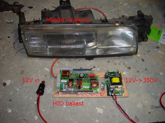
230VAC enters the ballast at the lower left corner. There it is EMI filtered with some inductance and capacitance. Directly after that is the PFC boost stage (inductor in the lower middle section of the PCB, which gives +390VDC. On the right is the Buck inductor.
Both inductors have a few-turns auxiliary winding. I suppose the winding on the boost inductor is for powering the control circuitry, and the winding on the Buck inductor is for sensing zero current.
Then, on the top half of the PCB there is the full-bridge inverter using 2x IR2153D, the igniter (Red capacitor, inductor on the left, SIDAC near the inductor) and a vertical PCB with the control logic on it. The control logic consists of a lot of LM224's and a lot of small devices (R's, C's, T's)
Small update: I decided to use the ballast I have since building myself a more compact ballast proves to be quite difficult. A ZVS inverter with ignition using the same transformer is a problem; high Vdsmax MOSFET's are needed which dissipate too much when running normally. And control of all that is not very easy either. And to top it off: the lamp does not seem to like a 300kHz waveform applied; especially during warmup the arc looks strange. Probably acoustic resonance.
My next attempt will be a converter running at 1MHz (to avoid acoustic resonance in the discharge) with external igniter, but before such a beast is working reliable, a lot of time has passed by. Therefore I built myself a 260VDC output push-pull using an UCC2808 and voltage mode control (I fed the RC waveform to the CS pin through a resistive divider), so I can use the existing ballast. I will have a problem fitting it on the motorbike, though.
On this picture it is powering a 60W 220V bulb; things stay nice and reasonably cool during the 2-hour period I left it running on the bench. The total circuit measures about 70x70x35mm.
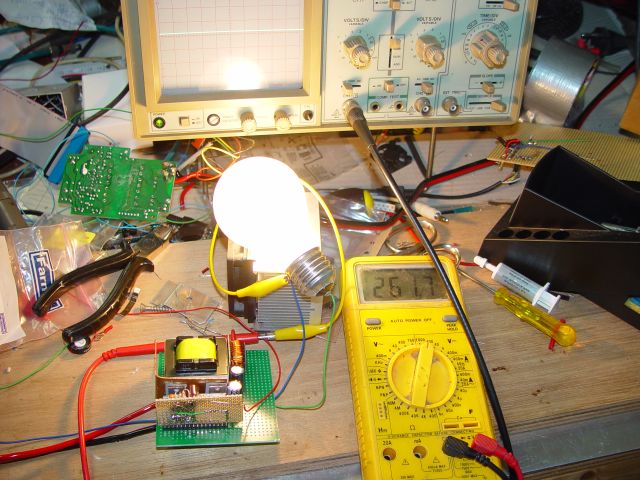
One question: I'm using voltage mode control since I lack low-valued current sense resistors. Duty cycle is about 80%. That allows some time for the transformer core to reset the small flux imbalance that always occurs. But I wonder if it's enough? I never really used voltage mode control before in these applications. Transformer primary waveforms look symmetrical on the scope and I have not noticed signs of core saturation such as a rising current draw and excessive heating of one MOSFET, but my scope is not that good.
My next attempt will be a converter running at 1MHz (to avoid acoustic resonance in the discharge) with external igniter, but before such a beast is working reliable, a lot of time has passed by. Therefore I built myself a 260VDC output push-pull using an UCC2808 and voltage mode control (I fed the RC waveform to the CS pin through a resistive divider), so I can use the existing ballast. I will have a problem fitting it on the motorbike, though.
On this picture it is powering a 60W 220V bulb; things stay nice and reasonably cool during the 2-hour period I left it running on the bench. The total circuit measures about 70x70x35mm.
One question: I'm using voltage mode control since I lack low-valued current sense resistors. Duty cycle is about 80%. That allows some time for the transformer core to reset the small flux imbalance that always occurs. But I wonder if it's enough? I never really used voltage mode control before in these applications. Transformer primary waveforms look symmetrical on the scope and I have not noticed signs of core saturation such as a rising current draw and excessive heating of one MOSFET, but my scope is not that good.
I am surprised to see that syringe of heatsink compound on your bench. I can't remember how long ago I purchased mine.🙂
Well, actually I used the thermal goop more as glue to 'stick' the isolation plates to the MOSFET's during assembly of the heat sinking.
hello DaBit,
I am also developing such ballast and using UCC2305 but messed up with igniter.
I dont know the part number of commonly used sidacs. can you suggest some which can be eaisly available.
I am also developing such ballast and using UCC2305 but messed up with igniter.
I dont know the part number of commonly used sidacs. can you suggest some which can be eaisly available.
I ended up making a new 12VDC->250VDC converter with a couple of smaller EFD20 cores. These cores (and capacitors) were placed on the board in such a way that they fitted in the voids of the original HID-ballast.
Thus, I could mount the 12V->250V PCB on top of the original HID PCB without needing extra space.
The assembly was small enough to fit on the motorbike, so I didn't bother too much making my own ballast.
However, I did play around a little with a HF approach, using a variable frequency around 200kHz on the primary and a resonant series LC on the secondary with the lamp parallel to the capacitor of the LC circuit.
When the frequency is on the LC resonant frequency, the voltage over the lamp increases a lot, and it should ignite. The resonant capacitor contains some energy to get the arc going. When ignited, the frequency can be tuned up or down to regulate lamp power.
I managed to ignite and burn the lamp a couple of times using a variable resistor for the frequency, but efficiency was quite low. And since this experiment was born just out of curiosity I didn't investigate it any further.
However: using this method it should be possible to make a 12V HID ballast the size of a matchbox. A high frequency with some FM lowers/eliminates acoustic resonance problems in the arc discharge, and it keeps the magnetics small. Efficiency around 70% should be possible also. Not that high, but often enough.
OK, now back to the trigger diodes. I personally have no problems obtaining them. SGS-Thomson DB3 is widely available, and distributors such as Farnell stock an even wider range.
- Status
- Not open for further replies.
- Home
- Amplifiers
- Power Supplies
- PSU and Igniter design for metal halide lamp.