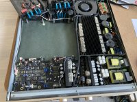
Just gotten a used PSSO DP-2400 where one channel is not working.
Anyone who has experience with this amp?
It seems that one of the modules have been changed already, as on of the modules are using a T157-2 output core, while the other a T130-2.
Modules are unfortunately fully molded in epoxy.
Any ways og getting this off ?..... would guess not ... pretty tough stuff
Anyone who has a service manual or schematics?
As for information:
I employs a full bridge, and by one company's suggestion for spare parts, sues IR2110 for driver and 8 x IRFP4227 for output mos
Rated at 2 x 650 W in 8 ohm
Attachments


Modules are unfortunately fully molded in epoxy.
Any ways og getting this off ?..... would guess not ... pretty tough stuff
Forget about trying to remove, too much risk of physical damage to the board, there are chemicals that claim to be able to remove it , but they risk damage to the pcb or the natural insulation of same.
you cant use longtime Class D amp with SMD parts
without fully molded in epoxy
Humidity amd Dust will destroy quickley
> IR2110 for driver and 8 x IRFP4227
normally using IR 2010 and IRFP250N, standard china reference design, some china factory dont molded in epoxy
no way for service throw it away
you need trough hole parts build Class D amp for reliable long time use
but this amps are pricey
Ahhhh a bit too soon to give up!
I would think most "modern" class d amps in the pro field uses SMD to a large extend.
Of course Fets and surrounding components should be larger through hole components to be able to get rid og the heat.
I looking for the Service Manual, as it actually might not be the modules I think, but could be the control circuit.
I think it might be that the amp module never gets a start signal?
Maybe the SD signal from the IR2110 is controlled by the circuit off the module?
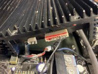
There is a a 10 pin connector going in to the module besides the audio input connection.
Would be super helpful to know what this carries.
I can see to the the connecting wires have been removed in the 10 pin connector (clipped off) ... why??
I would think most "modern" class d amps in the pro field uses SMD to a large extend.
Of course Fets and surrounding components should be larger through hole components to be able to get rid og the heat.
I looking for the Service Manual, as it actually might not be the modules I think, but could be the control circuit.
I think it might be that the amp module never gets a start signal?
Maybe the SD signal from the IR2110 is controlled by the circuit off the module?
There is a a 10 pin connector going in to the module besides the audio input connection.
Would be super helpful to know what this carries.
I can see to the the connecting wires have been removed in the 10 pin connector (clipped off) ... why??
Found out a lot of things today:
One input on the input board was damaged; a burned TVS and a 10k resistor. This is why no signal came through from the XLR on the back to the amp.
Changed the resistor and left the TVS out (until i get a suitable one). Also changed the opamp as I think it might be damaged as well.
Also found that someone trying to repair the beast had turned the connection from the input board to the amp module 180 deg.
Also seem that someone have changed one of the linear regs on the input board (but obviously not found the TVS and resistor) ...
Anyway now both channels work from XLR through the input section and to Amp module input.
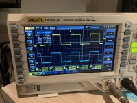
The "older" module works, and starts nicely up. Fs around 300 kHz. Sound through to the speaker.
The "newer" amp module does not start. I'm thinking that:
- either it is damaged, which seems not so likely as there appear no damage.
- the connection is different for the 2 modules and somehow it does not get the right signal to start.
.....
Found some pictures of an older DP-1200 module without black putty, but it does not really give any good suggestion. A lot seems the same but e.g. the connecter is a 8 pole one, where the one on my DP-2400 is a 10 pole one ..... so probably not the same at all .... also 2 pins on the 1200 seems to be used for a thermal switch
PD-1200 link: PA Verstärker PWM Class D/ein Kanal defekt, Elektronik (Stereo&Surround) - HIFI-FORUM
One input on the input board was damaged; a burned TVS and a 10k resistor. This is why no signal came through from the XLR on the back to the amp.
Changed the resistor and left the TVS out (until i get a suitable one). Also changed the opamp as I think it might be damaged as well.
Also found that someone trying to repair the beast had turned the connection from the input board to the amp module 180 deg.
Also seem that someone have changed one of the linear regs on the input board (but obviously not found the TVS and resistor) ...
Anyway now both channels work from XLR through the input section and to Amp module input.
The "older" module works, and starts nicely up. Fs around 300 kHz. Sound through to the speaker.
The "newer" amp module does not start. I'm thinking that:
- either it is damaged, which seems not so likely as there appear no damage.
- the connection is different for the 2 modules and somehow it does not get the right signal to start.
.....
Found some pictures of an older DP-1200 module without black putty, but it does not really give any good suggestion. A lot seems the same but e.g. the connecter is a 8 pole one, where the one on my DP-2400 is a 10 pole one ..... so probably not the same at all .... also 2 pins on the 1200 seems to be used for a thermal switch
PD-1200 link: PA Verstärker PWM Class D/ein Kanal defekt, Elektronik (Stereo&Surround) - HIFI-FORUM
Attachments
Hello Baldin,
I've just found your post when I was searching for info's/schematic of PD-2400 too.
Mine has a problem with the power supply. I've found 2 defective HEXFETs.
I decided to offer the device as a spare parts donor.
So if you are interested: ebay.de/itm/224656516712
I've just found your post when I was searching for info's/schematic of PD-2400 too.
Mine has a problem with the power supply. I've found 2 defective HEXFETs.
I decided to offer the device as a spare parts donor.
So if you are interested: ebay.de/itm/224656516712
Hi sbia
Might be of interest, if I can't get the module to work. Where do you live in DK?
Still think it's a matter of getting it started in the right way.
Do you know if the amp modules are ok??
Could I possible get you to take a good picture of the input board and the connector/connection to the modules??
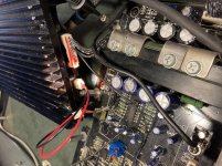
Think you mode is an older version of the DP-2400 ... mine looks like this picture 😉
I think the connections are different from model to model, and from version to version.
There is a very small extra pcb in my amp, which I think is the Enable signal.
It seems to be a newer modification .... pic 9539 lower right corner
Might be of interest, if I can't get the module to work. Where do you live in DK?
Still think it's a matter of getting it started in the right way.
Do you know if the amp modules are ok??
Could I possible get you to take a good picture of the input board and the connector/connection to the modules??
Think you mode is an older version of the DP-2400 ... mine looks like this picture 😉
I think the connections are different from model to model, and from version to version.
There is a very small extra pcb in my amp, which I think is the Enable signal.
It seems to be a newer modification .... pic 9539 lower right corner
Attachments


- Home
- Amplifiers
- Class D
- PSSO DP-2400 repair