phase_accurate said:
Does this have anything to do with the place you moved to ???
Regards
Charles
...ohh yes. And a lot of freshers to train...
(Sorry thread starter for the OT !)
What are you doing there ? Is it interesting ?
Regards
Charles
What are you doing there ? Is it interesting ?
Regards
Charles
phase_accurate said:(Sorry thread starter for the OT !)
What are you doing there ? Is it interesting ?
Regards
Charles
Hi Charles,
...I will send you a mail. I do not want to kill this thread.

bjorno said:Rocky,
In this case I think you should use transformers and simply program your Orcad ideal transformers to Bl:1 and 1:S.
Yes, indeed, the transformers in the model are ideal transformers, and non-ideal behaviour such as inductance etc would make the transformer not fulfill its purpose in the model.
Svante,
in your tech doc, you are definig Rms=Rts-Res, yet Rts<Res so Rms becomes a negative number. something wrong there?
PSpice does not have a model for an ideal transformer, but there are available documentation on how to make one from two inductors.. However, I made one using a current controlled current source and a voltage controlled voltage source (back-to-back, pri voltage sets sec voltage - sec current sets pri current), so I now have a perfect transformer model with absolutely no non-ideal behaviour 🙂
I also have a working gyrator model now, made from controlled sources as well, so I am all set to implement the Basta! circuit 🙂
I think the plan will be to use a 6.5" passive radiator on the back side of the box, or is this a bad idea on a bookshelf speaker?
Rocky said:Svante,
in your tech doc, you are definig Rms=Rts-Res, yet Rts<Res so Rms becomes a negative number. something wrong there?
In real life Rts is always >Res. If you run Basta the opposite may happen if you enter a Qts value larger than Qes, and this corresponds to faulty input parameters, which are not possible in real life, and this is indicated by a negative number in red text for Qms.
Hmm, did that answer the question?
Yes it did, i've been staring myself blind on numbers these last days and make silly mistakes.. 
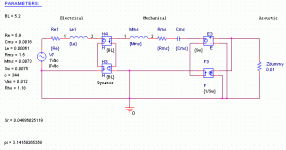
My current circuit behaves strangely, it migh be because I've not yet implemented the acoustic side properly, but the impedance peak at Fs don't seem to reach the same amplitude as my basic driver model (the one my current crossover design is made with).
Does it look faulty?

My current circuit behaves strangely, it migh be because I've not yet implemented the acoustic side properly, but the impedance peak at Fs don't seem to reach the same amplitude as my basic driver model (the one my current crossover design is made with).
Does it look faulty?
Attachments
Here's the driver specs in case anyone need them to comment.
http://www.seas.no/seas_line/woofers/H1141.pdf
(and here is the tweeter as well...)
http://www.seas.no/seas_line/woofers/H1141.pdf
(and here is the tweeter as well...)
Hmm, I don't have much experience with PSpice, but it looks ok apart from one thing. The gyrator is Ok, I think, a current on one side generates a voltage on the other side. But the transformer... It is assymetrical. That is not the case in the real world. I would expect the voltage on the output to be proportional to the voltage on the other side. Both ways. And I suggest that you model radiation impedance as a resistor in parallel with a capacitor.
Lets see, apart from the inverted current direction (which is fixed now) the transformer secondary sets primary voltage with "gain" of Sw (membrane area), the primary side current sets "gain" on secondary current to 1/Sw... You are indeed right. I should set the gain to Sw on the current source as well..
It still appears the impedance peak is much weaker than that of my old circuit (about half the expected peak impedance at Fs). Will this be solved when I work out the acoustic circuit you think?
It still appears the impedance peak is much weaker than that of my old circuit (about half the expected peak impedance at Fs). Will this be solved when I work out the acoustic circuit you think?
Svante; In the mechanical part of the circuit, I notice you use Mms (weight incl. air load) for the coil, while Marshall Leach uses Mmd (weight without air load) for the same component (same gyrator based circuit, only exception is Mmd vs Mms). Although these numbers are only slightly different, I would presume one would me "more correct" than the other.. which one?
Another issue I'd like some feedback on is the mutual coupling between the woofer cone and the vent. Prof. Leach uses two koupling coefficients in his model, being:
kw=3*pi*Aw/16d (coupling port to diaphragm)
kp=3*pi*Ap/16d (coupling diaphragm to port)
Aw is the piston radius of the woofer diaphragm, Ap is the radius of the port.
In his publication "Computer-Aided Electroacoustic design with SPICE", Prof. Leach uses an example model with a cylindrical vent placed on the front baffle. My question is: can I use the same analysis with a rear-mounted cylindrical port, if calculating the physical distance between the two centerpoints as the shortest distance around the outside of the box?
edit: forgot to mention an essential of the equations: d is the distance between the centers.
Rocky said:Svante; In the mechanical part of the circuit, I notice you use Mms (weight incl. air load) for the coil, while Marshall Leach uses Mmd (weight without air load) for the same component (same gyrator based circuit, only exception is Mmd vs Mms). Although these numbers are only slightly different, I would presume one would me "more correct" than the other.. which one?
Hmm, maybe it is just my definition of Mms that is odd... If you look under the equivalent circuit for the loudspeaker in the tech doc, you can see that the air load is removed from the total oscillating mass, and that that is then used as the Mms in the diagram. (Mms=...)
Put short: Leach and I do it the same way, without the air mass.
The woofer model is really coming together nicely now.. I can probe volume velocities, acoustic pressures, and get a whole lot of information I still don't have a clue on how to put into use  This is way cool! Still some stuff left to implement into the model though.. Like lossy voice coils..
Thanks alot for the help you've provided so far Svante, your advice has been of great value. I probably have a million questions right now, as I'm fiddeling around with my new model trying to understand it properly... but instead of bombarding you with a bunch of questions I haven't thought properly through, I need to figure some of them out for myself.. Anywayz; Tack så mycket för dina utmärkta och innehållsrika svar på mina frågor.. Det har varit oerhört värdefullt. 😉
 This is way cool! Still some stuff left to implement into the model though.. Like lossy voice coils..
Thanks alot for the help you've provided so far Svante, your advice has been of great value. I probably have a million questions right now, as I'm fiddeling around with my new model trying to understand it properly... but instead of bombarding you with a bunch of questions I haven't thought properly through, I need to figure some of them out for myself.. Anywayz; Tack så mycket för dina utmärkta och innehållsrika svar på mina frågor.. Det har varit oerhört värdefullt. 😉
Well, another update, that is if anyone is still reading this thread..
The mathematica formula sheet is completed (that was *alot* of formulas ) so that when I change vent placement/size/tuning, box size, baffle size, box depth, etc, it automatically calculates all the variables. They are a pain to change even with this method (Ctrl+C+V 🙄 ) as there are 21 variables in the simulation parameter list, being;
Le,Re,Bl,Mmd,Cms,Sw,Mab,Cab,Ral,Map,Ma1p,Ra1p,Ra2p,Ca1p,Ma1w, Ra1w,Ra2w,Ca1w,kw,kp
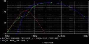
Simulation results appear similar to what my WinISD suggests. I also added the complex LAPLACE functions so now I can easily probe the SPLs from the vented box system using PSPICEs VDB probes.
This is what the L15RLY looks like (box tuning in no way optimized, I hardcoded tuning freq and chose 50Hz by coincidence, so this is *not* a maximum-flat Butterworth alignement.). This is without any crossover network.. The high frequency rolloff seems very much like what's in the datasheet of the driver if one ignore the *big* breakup nodes.. Impressing The SPL seems a bit low though.. this is supposed to be 1m in front of the driver.
The mathematica formula sheet is completed (that was *alot* of formulas
 ) so that when I change vent placement/size/tuning, box size, baffle size, box depth, etc, it automatically calculates all the variables. They are a pain to change even with this method (Ctrl+C+V 🙄 ) as there are 21 variables in the simulation parameter list, being;
Le,Re,Bl,Mmd,Cms,Sw,Mab,Cab,Ral,Map,Ma1p,Ra1p,Ra2p,Ca1p,Ma1w, Ra1w,Ra2w,Ca1w,kw,kp
Simulation results appear similar to what my WinISD suggests. I also added the complex LAPLACE functions so now I can easily probe the SPLs from the vented box system using PSPICEs VDB probes.
This is what the L15RLY looks like (box tuning in no way optimized, I hardcoded tuning freq and chose 50Hz by coincidence, so this is *not* a maximum-flat Butterworth alignement.). This is without any crossover network.. The high frequency rolloff seems very much like what's in the datasheet of the driver if one ignore the *big* breakup nodes.. Impressing
 The SPL seems a bit low though.. this is supposed to be 1m in front of the driver.
Attachments
Rocky said:The woofer model is really coming together nicely now.. I can probe volume velocities, acoustic pressures, and get a whole lot of information I still don't have a clue on how to put into useThis is way cool! Still some stuff left to implement into the model though.. Like lossy voice coils..
Yes, it's cool I agree. And once you have measured the LF response of a speaker and seen the agreement, it is even cooler. As you obviously understand swedish, you might also benefit from reading this loudspeaker lab:
http://www.speech.kth.se/courses/1400/htlab.pdf
An interesting measurement method for the LF response of a loudspeaker is described there. It uses a microphone inside the box, which makes the room not matter at all.
...but don't forget to simulate the baffle step... 😉
Rocky said:---snip-- The high frequency rolloff seems very much like what's in the datasheet of the driver if one ignore the *big* breakup nodes --snip--
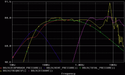
Some might call the above an overstatement, here is the yellow aneholic response on a IEC 268-5 baffle (apart from the low end, which is my simulation). Hey, if ignoring the slightly ragged top end, this driver could be used full range! 😀
The pink curve in the background is the tweeter showing where it's at. It is connected to the crossover from page 2, and has baffle diffractions accounted for (although they will need modifications as I will change the baffle). Woofer is still bypassed from the filter, obviously.
edit: typos
Attachments
Woofer connected to the original (now preliminary) crossover. Still woofer baffle step has not been taken into account. I guess I will have to subtract the step of the IEC baffle and add the step of my BR box, since I can't measure for myself.. I'll need to read some more theory before I have the answer to that one.
Forgot to mention, baffle step included on the tweeter response is slightly off-axis (reason for the drop at 15kHz). It is the FTABLE from the initial simulation, where I had the plan I would slope the baffle.
Forgot to mention, baffle step included on the tweeter response is slightly off-axis (reason for the drop at 15kHz). It is the FTABLE from the initial simulation, where I had the plan I would slope the baffle.
Attachments
- Status
- Not open for further replies.
- Home
- Loudspeakers
- Multi-Way
- PSpice crossover design


