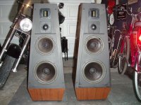
Pyramid? Where you thinking of something like the Nestorovics pictured here? First time I've seen them with the sort of hats on top:
SoundStage! WCES 97 Show Report
They usually look like this:
SoundStage! WCES 97 Show Report
They usually look like this:
Attachments
I was thinking others might want to "clone" them. I've always thought Madisound or PE should offer DIY clones of some of the best classics. Madisound could easily have the PSB woofer cloned, in fact I'd prefer a 12" for a bit more headroom, NOT that the PSBs are lacking!
Cloning The Gold woofer
Pete, great idea to clone the Gold's woofer. It is a classic! This is a powerful driver. I don't know if hard wiring the new crossover made the diff but the bass lines I have been hearing are tighter, deeper and stronger than what I would ever expect a10" woofer to do. Since the crossover point of the woofer is 200hz, why not two of these fine drivers for a bit more head room?
Phil, we need to see some pics of those new woofers.
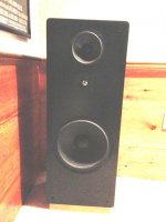
I helped a friend clone them around 1997 and just got back in touch with him to ask for some pictures. The mid and tweeters are the stock Vifas that I mentioned earlier in the thread. The woofer is the NHT 1259 that I found would have some peaking around 60 to 150 Hz in a 90 liter enclosure that makes up to some extent for the fact that it is so inefficient. We used a heavy laminated steel woofer inductor also to help get back some sensitivity. The larger 12" woofer with probably twice the throw of the PSB woofer should easily handle 500-1000W peaks in the bass. We vented it out the back, tuned to about 25 Hz. Enclosures are the old Madisound 90 liter towers.
I would probably not use a similar woofer to the 1259 today, but it worked out just fine.
The mid chamber was partitioned off with a diagonal shelf from the back upper corner to just below the opening for the mid driver in order to leave the most volume for the 1259 woofer. The PSB used a simple shelf partition. I think we padded the mid and tweeter with Lpads adjusted them to obtain the same tonal character as the actual PSBs and then measured the pads and put in fixed resistors. I don't remember exactly where we put the Lpads but I simulated them first in CALSOD to be sure that the response shape was not altered too much.
Attachments
Last edited:
Hi,
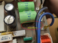
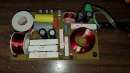
I am wondering if someone may have a schematic with the parts description of the original Stratus Gold crossovers. I have a set I am trying to get back to the original state, and there appears to be a part missing that should be next to the two large green 4uf caps, and there is an additional 18ohm resistor that has been laid across two of the 1.8ohm resistors.
Any help is greatly appreciated.
JD
Attachments
@WJD from what you've shown us yours seem to be built exactly like mine which was
very slightly different from the OP's pair. Mine had the two 4uF in parallel on the tweeter
but I could not read the "trim" value but the stack measured as 8.2 uF. You could probably
add .18 or .22 uF there.
I think that the resistor is also a trim value, mine had two 1.8 ohm 10W in series with the
18 across them - same as yours.
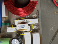
@PB2. Hello, I know this is an old thread, but you folks are talking about the speaker I currently have... 30 yo PSB Stratus Gold i. Never done recap on anything before, so please forgive my ignorance. Planning to replace caps and resistors. Can you tell me what 20W 1omega 3 means? Google provided various answers, such as 20watts, 1ohm, and 3% tolerance. Or 20watts, 1.3ohms. Which is correct? Thanks in advance.
Attachments
Omega is used in place of the decimal point in resistance values.
Is there anything wrong with those resistors?
Is there anything wrong with those resistors?
@AllenB. Thank you for the note. Physically, the resistors (and all other components) looks fine. In the course of the decades past, the speaker's sound quality may have been slowly changing. If one were to ask me, they still sound mighty fine today. From what I've read, electrolytic capacitors should be replaced after a certain time. Since the board is already out, thought I might as well do what I can that doesn't require major surgery. Should I only replace the 6 electrolytic capacitors and call it a day?
Those wirewound resistors are known for long term trouble free operation as long as they aren't abused, and even then they can take some. If you want to make sure, you can see they measure as expected.
You might use your sense of smell to detect burning. It's unlikely the inductors are damaged but it wouldn't be easy to tell by sight. Otherwise they shouldn't need replacing.
You might use your sense of smell to detect burning. It's unlikely the inductors are damaged but it wouldn't be easy to tell by sight. Otherwise they shouldn't need replacing.
Hello. I did the smell test and there's no burning odor.
While looking for the electrolytic capacitors replacements, was surprised at how physically LARGE the ClarityCap caps are. The original Hanlan electrolytic caps are: 4 x 100uF 100V; 1 x 10 uF 100V; and 1 x 1.5 uF 100V. The diameter of the ClarityCap for 10 uF is 50mm! The orig Hanlan is only 15mm. Can you maybe point me to something that might fit on the pc board?
While looking for the electrolytic capacitors replacements, was surprised at how physically LARGE the ClarityCap caps are. The original Hanlan electrolytic caps are: 4 x 100uF 100V; 1 x 10 uF 100V; and 1 x 1.5 uF 100V. The diameter of the ClarityCap for 10 uF is 50mm! The orig Hanlan is only 15mm. Can you maybe point me to something that might fit on the pc board?
Thanks for the Nichicon info. Yes, it would be simpler just to replace electrolytic with same. Are there non-electrolytic caps that have smaller footprints? Hoping to make some improvement over the original crossover setup.
Electrolytics were invented to reduce the size of capacitors. If size is important you could use the minimum reasonable voltage rating.
- Home
- Loudspeakers
- Multi-Way
- PSB Stratus gold X-over help