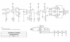
I have completed a 5E3 build and was going to follow up with a CJ11. The schematic for the CJ11shows a center tapped 5V winding for the GZ34 rectifier, with the HV coming from the center tap. On the 5E3 there is no center tap on the 5V winding, and HV is taken from Pin 8 of the 5Y3GT rectifier. The CJ11 PS transformer HV is 290-0-290, while the 5E3 is 355-0-355.
I believe I understand the differences of the 5Y3 vs 5AR4 (the construction,voltage drop, and current).
Is the center tapped 5V used to have less AC filtering (2.5V vs 5V) on the HV? Or lower HV?
My PS transformer (290-0-290) does not have the center tapped 5V. Would it be safer to substituted the 5Y3 and take HV from Pin 8?
Attachments
It makes hardly any difference. On paper the filament CT is a little less 60Hz in the ripple; I once poked somebody with a good oscilloscope and we could hardly see the difference.
The 5vAC is not referred to ground, it doesn't contribute ripple. The heater is of course pulsing on and off at 60Hz, but it has such thermal inertia (momentum?) that conduction doesn't vary much at all. So I agree with PRR, it won't make a difference.
You can wire any rectifier tube you like from the center tap, or you can tape off the center tap and just wire to pins 2 or 8 like the vast majority of amps. WHatever is convenient. If your chassis is already wired, leave it as is.
Remember, this is just a guitar amp, not some NASA lab equipment.
In all my decades, I have seen very few CT 5v windings.
The schematic shows a directly heated rectifier but the GZ34 is an indirectly heated type.
The cathode sleeve is connected to pin 8 and this is where you should take the HT from.
Should you take the rectified dc from pin 2, the dc flows through the filament on top of the 5Vac, heating it up more. A 5E3 won't draw a lot of HT current, so it shouldn't be a real problem.
However, consider the maximum load for a GZ34 of 0,25A on top of the 1,9A heater current. That is 13% overcurrent.
With directly heated rectifiers like the 5Y3 this effect is less and the maximum current compared to heater current even less, so no worries there.
There is of course a larger voltage drop, lower HT and more sag on loud notes, compared to a GZ34.
The 5vAC is not referred to ground, it doesn't contribute ripple. ..
Assume the filament emits over its whole length. Assume we only connect ONE end to extract the DC current. There is a 60Hz component added to the 120Hz component.
Checking back with Steve, he now remembers admitting that there "is" such a 60Hz component, but it is at the limit of eyeball observation. Assuming the 120+Hz partials are filtered, the 60Hz part will be insignificant.
- Home
- Live Sound
- Instruments and Amps
- PS tube rectifier question