So a little background. I have used AB International amps in the past and have recased a couple of 600As to power my modded Carver Amazings and they sound amazing. I’m now on a mission to recased a 1100A to power my sub towers.
I purchased one cheap none working. When I got it some of the power supply caps where installed backwards and burnt up a couple of the main traces between the transformer inputs and the rectifiers. I fixed the traces and installed new main caps. At J2 I have HV=109ishvolts at pin 5 and 7 to ground. I also have LV=53ish volts at pins 4 and 8 to ground. My question is could anyone tell me what the voltages should be at pin 2 (mute) and pin 3 (latch)? Any help would be hugely appreciated!View attachment 1361934
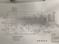
I purchased one cheap none working. When I got it some of the power supply caps where installed backwards and burnt up a couple of the main traces between the transformer inputs and the rectifiers. I fixed the traces and installed new main caps. At J2 I have HV=109ishvolts at pin 5 and 7 to ground. I also have LV=53ish volts at pins 4 and 8 to ground. My question is could anyone tell me what the voltages should be at pin 2 (mute) and pin 3 (latch)? Any help would be hugely appreciated!View attachment 1361934
Attachments
Last edited:
Hi Turbo,
Mute
Following the schematic from J2 pin2 to the bottom rigth J9 pin4 you can find it connects over a 3k3 resistor to a cathode of a LED, the other side of the LED is ground. So the Mute signal is going to be negative compared to GND. Given the date of the schematic being 1992 I assume this led is an old fashioned red (1.8 V) or green (2.1 V) LED that is fed about 15 mA of current. Using Ohms law this would btring us in the ballpark of -50 V for the Mute signal to lit up the power LED. Careful, it is minus 50 V.
You write that on the low voltage side the negative of the bridge D2 is at 53ish. I believe you mean -53 V. This connects over R15 (1.6k) to the mute signal. This confirms that the mute signal is at about -50 V.
Latch
Following the schematic from J2 pin3 to R16 resistor a 2k and then to the anode of the LED in the optocoupler IC1 over to the -53 V on bridge D2. I can't read the type of IC1 and therefor can't check the datasheet to verify how much current the LED should receive. Assuming it is an IR LED of 1.5 V taking 15 mA and given the resistor of 2k I would say that the Latch signal is at about -20 V when the optocoupler is activated. It can be anything lower till -53 V when the opto is not activated. Check the datasheet for the optocoupler to make sure.
Thank you for your response. I was having a no output situation but had input signal to the output boards and assumed it might be one of those two pins causing the issue. After much head scratching and further investigation I found the issue. The output boards used both XLR and 1/4” jack inputs. I removed both from the board and just soldered directly to the board where the XLR jack was. Come to find out the signal path runs from the XLR jack, through the 1/4” jack and then onto the boards input section. This wants in the schematic but finally figured it out and got them playing.
Thanks again though!

Thanks again though!