I am trying to improve my scratch built GG's channel separation. Among other factors, the psu is a place to work on. Currently, it use a single psu for both channels. Reading from others posts, I understand that one way to improve is to let each channel has its own final stage in the ripple filter.
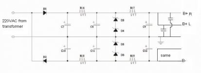
The current schematic is here. Zener is 100V each, B+ and B- required are 200V. All cap shown are each 3X100uF (i.e. total 18 cap). I am thinking of spliting the last stage cap (i.e. C9 and C12) and use the cap for each channel like in the "after" image. So C9 C12 become 2X100uF and new cap in the scheumatic is 1X100uF. Do you think it will work?
By the way, I found V drop across R17 R19 which make the B around (195V). Can I move it before the zenor?
Attachments
why not use a complimentary pair of high voltage transistors as series pass elements? or maybe power Mosfets?
EDIT: are you going to use a transformer for that?
EDIT: are you going to use a transformer for that?
Sorry... what is a GG? 
And if I'm reading right you're trying to directly rectify line voltage. VERY VERY DANGEROUS
And if I'm reading right you're trying to directly rectify line voltage. VERY VERY DANGEROUS
I’m sure you don’t mean that, but your schematic appears to be drawing AC straight from the wall socket, which is obviously dangerous. 😱
Either revise your schematic or withdraw it. In any case mods would be doing that soon
Either revise your schematic or withdraw it. In any case mods would be doing that soon
GG i assume is Grounded Grid.
And to reinforce... i sure hope that 230VAC is coming from a transformer secondary. Anything else gets you into the Darwin Awards (ie high likliehood of death
dave
Edit: i added a notation to the drawing.
And to reinforce... i sure hope that 230VAC is coming from a transformer secondary. Anything else gets you into the Darwin Awards (ie high likliehood of death
dave
Edit: i added a notation to the drawing.
Oh dearsenderj said:Nobody answer just because I made a mistake?
 I dont think its like that!
You may consider branching out just after C2. Each rail its own Zener string. C2>Rx2>C3x2>Zx2>C4x2 . What B+ are you looking at ? You can be comfortably in the region of 200~220 VDC. Do you have a CT Power TX secondary? Then you may consider using a bridge.
carbato,
Thank you for the reply. By C2, I guess you mean the second stage of the filter (i.e. C8 & C11). Am I right?
For the C2>Rx2>C3x2>Zx2>C4x2, do C3 and C4 be the same value as C2? Can they be smaller?
I don't know what is CT Power TX secondary. If it means another 220VAC output, then I don't have. There is only one set of 220VAC from my transformer, so I cannot use 2 bridges.
ackcheng,
Have you build your shunt reg? If so, what is your comment? Any kit available for the shunt reg?
Have you build your shunt reg? If so, what is your comment? Any kit available for the shunt reg?
Currently building one. Have not tested yet. But the topology seems good. You can download the manuel here
http://www.euronet.nl/~aespreng/Shuntregv11d/Manual.pdf
If you are in HK, you can also contact me by email!
http://www.euronet.nl/~aespreng/Shuntregv11d/Manual.pdf
If you are in HK, you can also contact me by email!
You can decouple very simply by adding a resistor in series with the feed to each of the caps you split out. Figure that if you size the resistor to drop 5-10V (use Ohm's Law), you'll isolate the channels pretty well.
- Status
- Not open for further replies.
- Home
- Amplifiers
- Tubes / Valves
- PS for GG - look for better channel separation