Reading through old Audiocraft magazines Feb 1956... I came across something I've never seen before, a feed through resistor over a power supply CLCR train where a bit of 180 degree hum is injected front to back feed-forward. The problem is that you need to tune the feed forward resistor. Is this a reliable design easy enough to implement? I could see tuning it safely by hooking it to a low voltage 6.3v AC transformer with a pot and the scope, adjusting the hum balance, then replacing the pot with a fixed resistor and then applying B+ voltages. I clipped the section fig 10 and circled it here.
Why do we not see this very often? I've never seen it or noticed it.

Why do we not see this very often? I've never seen it or noticed it.
I can see it helping best with valve rectification where the first cap is usually a small value so as not to overload the valve.
The phase shift may not be 180deg.
That article described a lot of options, but I don't know of any equipment that used that scheme of hum reduction. Rayma, I couldn't see any such circuitry in a quick look at Marantz amp schematics.
That article described a lot of options, but I don't know of any equipment that used that scheme of hum reduction. Rayma, I couldn't see any such circuitry in a quick look at Marantz amp schematics.
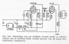
The ripple-injection to the screengrid of the preamplifier tube in this schematic (Philips, 1951) is ofcourse not identical to the arrangement presented by TS but it is comparable. The injected ripple counteracts the ripple that is induced through the screengrid of the power tube.
It was done like this in some AC/DC radios which (also) had to operate from low mains voltages (110 V). This arrangement made it possible to feed the screengrid of the power tube from the first electrolytic capacitor, despite the ripple that exists there. By doing so, B+ was as high as possible resulting in a bit more power output.
Note: The 300 Ohm resistor in the schematic represents the DC-resistance of the output transformer so there is not an actual resistor there.
Attachments
Last edited:
That concept in the article , like many others , are like the poor man's choice when you don't have good enough parts or you are too cheap . A normal good CLC filter doesn't have too much ripple , and there must be a series undecoupled high value resistor after which the cancelation voltage is applied , so it is for low current , aplications are limited . An extra , or two RC filters in chain and you don't even need that .
Last edited:
The ripple-injection to the screengrid of the preamplifier tube in this schematic (Philips, 1951)
Cool, do you have the exact reference for that image?
The image/schematic in post #5 is on page 322 of Part V of the Philips Series of Books on Electronic Tubes. The book is in Dutch though. I do not know if Part V was ever published in English.
Much of the series can be found here (I scanned parts IIIb and V, and found some of the other parts for this site): electron Tube Data sheets - PHILIPS' TECHNICAL LIBRARY - Series on ELECTRONIC TUBES
Much of the series can be found here (I scanned parts IIIb and V, and found some of the other parts for this site): electron Tube Data sheets - PHILIPS' TECHNICAL LIBRARY - Series on ELECTRONIC TUBES
Last edited:
RDH3 (p.200) had the simpler method to inject some hum in to the screen-grid with just a capacitor in parallel with the screen dropper resistor, but that may relate to a less well filtered screen and anode supply situation.
I was also confused by how the 180 degree out-of-phase is obtained... Is it because the feed forward loop spans exactly two of the capacitors at 90 degrees shift each?
To complement trobbins: John Broskie has a lot of posts on feed forward regulators, but as such are more complex than the circuit in the 1st post.
IIRC Zen Mod posted something similar for one of Nelson Pass' creations.
I'll post it here if I find it again.
I'll post it here if I find it again.
Phase shift across a part will depend on the reactance of the part at the 2nd harmonic frequency. A typical choke at 100-120Hz will impart an almost 90deg shift. An RC stage will impart a phase shift depending on the RC corner frequency.
I tried the "tuned choke" before, but its performance is very bad outside its tuning frequency. It could just have been me not optimising everything around (it was a guitar amp). Do you use it?
Phase shift across a part will depend on the reactance of the part at the 2nd harmonic frequency. A typical choke at 100-120Hz will impart an almost 90deg shift. An RC stage will impart a phase shift depending on the RC corner frequency.
I'd have to look at this on the scope, it sounds like the injected cancellation hum would be inaccurately off from 180 degrees wildly depending on what parts you used. Then when someone goes to repair the amp some day, replaces parts, the intended cancellation phase is different again.
Do you use it?
I tried it (the space inside the amp box was very narrow to use another choke or larger capacitors, so "tuning" helps to decrease hum), but not of my cup of tee.
It's working good, when the load current is -mostly- constant (for example preamp with CCS load), but in case of power amps (where the current is depends of the music) the transient behaviour of PSU output worse than in case of "classic" CLC smoothing.
Cancellation, right?
What is the group delay of the filter for all the frequency harmonics of the power mains frequency?
2x, 3x, 4x, etc.?
What is the group delay of the filter for all the frequency harmonics of the power mains frequency?
2x, 3x, 4x, etc.?
I've tried the 'tuned choke' setup.
Be aware that the choke inductance can change with operating condition (voltage across choke and DC current through choke), so it is advisable to measure the choke inductance under those default conditions (and that is not achieved by a simple LCR meter, so need something like https://www.dalmura.com.au/static/Choke%20measurement.pdf). Perhaps target the default conditions for amplifier idle operation if noticeable hum is the main reason for making this mod (ie. hum not so noticeable under high signal conditions where inductance may droop).
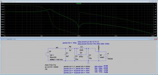
I'd recommend tuning the parallel cap to a bit under the 2nd harmonic, as that reduces the level of higher order harmonic bypass through the parallel cap, but still effectively lowers the 2nd harmonic (dominant) ripple level.
The subsequent filter cap (after the tuned choke) effectively suppresses higher order harmonics, as expected, and given those higher harmonics are already lower in magnitude then the outcome is a noticeable drop in rms ripple voltage.
There may be some benefit in adding some series R to the tuned cap, depending on the DCR of the choke.
The tuned cap may see quite a significant voltage across it, especially for choke input filter configuration, but possibly also during turn-on for a CLC configuration, so the cap AC voltage rating needs to be appropriate.
Be aware that the choke inductance can change with operating condition (voltage across choke and DC current through choke), so it is advisable to measure the choke inductance under those default conditions (and that is not achieved by a simple LCR meter, so need something like https://www.dalmura.com.au/static/Choke%20measurement.pdf). Perhaps target the default conditions for amplifier idle operation if noticeable hum is the main reason for making this mod (ie. hum not so noticeable under high signal conditions where inductance may droop).
I'd recommend tuning the parallel cap to a bit under the 2nd harmonic, as that reduces the level of higher order harmonic bypass through the parallel cap, but still effectively lowers the 2nd harmonic (dominant) ripple level.
The subsequent filter cap (after the tuned choke) effectively suppresses higher order harmonics, as expected, and given those higher harmonics are already lower in magnitude then the outcome is a noticeable drop in rms ripple voltage.
There may be some benefit in adding some series R to the tuned cap, depending on the DCR of the choke.
The tuned cap may see quite a significant voltage across it, especially for choke input filter configuration, but possibly also during turn-on for a CLC configuration, so the cap AC voltage rating needs to be appropriate.
Last edited:
- Home
- Amplifiers
- Tubes / Valves
- PS filtering with feed through hum cancellation