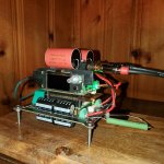
Kit acquired from @hifiamps (no affiliation otherwise). Original intention was to pair with Rasberry Pi, then I saw @6L6 implemented without. I used:
Mark’s kit so far bog stock
9V trafo
Simple LM317 PS graciously provided by @manniraj (he threw that in when I bought a working MiroAD1862 PCB and PSU1)
Amanero 384 combo input board, an Ali clone
IE socket and fuse holder sourced long ago from ApexJr.
A bit of scrap MDF board
Two issues now resolved- silkscreen on the input card connections didn’t match the ProtoDAC assembly instructions which is apparently a common problem. Searching terms on this forum informed how to move one wire. First fire up yielded a loud crackly sound both channels. @6L6 advised quickly and accurately to add a ground wire between input board and the Proto. Fixed!
So far only played through a scratch built El84 tube amp based on an early Mullard circuit and tiny full range bookshelf speakers, Dell laptop win11 straight in. Sound is very pleasing, quite prominent bass.
Quite something the ProtoDAC, four capacitors five resistors and a daughter card with eight little Philips Dac chips under $100. Next step to listen on the bigger system IronPre + biamped SIT amps.
Not sure if it would benefit from an AmyAlice filter- one is on the way from @ItsAllInMyHead
Thanks folks!

I have had a Protodac for over a year. It is combined with components from Ian Canada (PurePi II, ShieldPi, FifoPi Q7, ScPure Clocks, MonitorPi Pro) and a RPI3B+. All powered by an IfiPowerX SMPS.
I recently changed the WIMA MKP4 output capacitors for Jantzen Superior Z-Cap and most importantly I finally inversed polarity. That changed everything. Lots of bass, the soundstage is very good and the sound compares well to an excellent turntable. Zero fatigue. The music is sweet. I listen to music several hours a day.
I have compared this DAC to others X times more expensive and so far it is the Protodac that I prefer.
Attachments
Yes, the polarity inversion really makes a difference. I have assembled 4 ProtoDACs, varying components. All on RPis running MoOde. Reversing polarity with or without CamillaDSP is necessary.
I hadn't seen any other ProtoDAC threads with comments from @6L6, and would be interested in reading them, particularly regarding using a USB to I2S converter.
Skip
I hadn't seen any other ProtoDAC threads with comments from @6L6, and would be interested in reading them, particularly regarding using a USB to I2S converter.
Skip
Yes, the polarity inversion really makes a difference. I have assembled 4 ProtoDACs, varying components. All on RPis running MoOde. Reversing polarity with or without CamillaDSP is necessary.
I hadn't seen any other ProtoDAC threads with comments from @6L6, and would be interested in reading them, particularly regarding using a USB to I2S converter.
Skip
Regarding the OT. Not the complete DAC, but only eight additional passive components are required, and a standard Philips I2S signal. TDA1387 X8 module, I2S input to pins 1, 2, 3 (LRCK, BCK, DATA, with 100-430R serial decoupling resistors), ground pin 5, +5VDC pin 28 (2000uF decoupling cap), right channel out pin 6, left channel out pin 25. Simple, passive I/V with two 430R resistors from output to ground. Output coupling caps with PP film 3.3uF for 10k SS inputs, lower value for higher impedence inputs. A simple NOS DAC. Gerber for PCB. Build one and hear it for...
I'm not one for comparisons, but I will say that I have been glued in the lab, merrily puttering away at projects, absolutely loving the music that this is putting out. I'll drag it into the big system here over the weekend, I bet it's going to be a lot of fun.
The USB I2S is built around the PCM2706 and seems to just work and sounds great. USB in, 3 wires out. Good enough for me! Is so ridiculously cheap (less than five bucks on Ali) that there's no good excuse for not trying it. Will I try other input cards, yes, of course, but this thing is neat.
The USB I2S is built around the PCM2706 and seems to just work and sounds great. USB in, 3 wires out. Good enough for me! Is so ridiculously cheap (less than five bucks on Ali) that there's no good excuse for not trying it. Will I try other input cards, yes, of course, but this thing is neat.
Here you go @Skip Pack. Note @hifiamps ^ post, that input board is the one @6L6 used.
Thanks for the posts, I started on that thread last night but hadn't made it that far yet. I'll keep going. I have noticed that all my ProtoDACs are a bit output voltage challenged. I may just package my build with some 2022FE cards to get at least 2VDC rms out. It will be nice to have the flexibility of a standalone usb DAC
Skip
Skip
The TDA1387 is only capable of 3.5Vpp (1.24Vrms) before clipping with passive I/V. The DC output voltage compliance is 0 to 3.5V (data sheet page 8).@Skip Pack: I have noticed that all my ProtoDACs are a bit output voltage challenged.
What are 2022FE cards?
Thanks, The 2022 Front End is a discrete opamp that Nelson Pass designed that is very
flexible in gain and power requirements. It's dead quiet, makes a great line level preamp, is easy to build and cheap at the DIYAudio store. here's the writeup link:
Skip
flexible in gain and power requirements. It's dead quiet, makes a great line level preamp, is easy to build and cheap at the DIYAudio store. here's the writeup link:
Greetings.
I present the DIY FRONT END 2022.

EDIT: For current boards marked "V0R1" please find the changes and additional information in post #686 of this thread
https://www.diyaudio.com/community/threads/diy-front-end-2022.394339/page-35#post-7323986
I present the DIY FRONT END 2022.
EDIT: For current boards marked "V0R1" please find the changes and additional information in post #686 of this thread
https://www.diyaudio.com/community/threads/diy-front-end-2022.394339/page-35#post-7323986
- Nelson Pass
- Replies: 1,690
- Forum: Pass Labs
Skip
Changed output caps. Currently at the office, plugged into ACA w/ premium parts into Coral holey baskets.
Next I’ll try uninverting the speaker polarity. @abraxalito kindly suggested adding an LT3042 additional regulator card as the LM317 can benefit from further noise reduction. One is on order.

Next I’ll try uninverting the speaker polarity. @abraxalito kindly suggested adding an LT3042 additional regulator card as the LM317 can benefit from further noise reduction. One is on order.
Listening again through main biamped SIT system, subjectively finding the output capacitor change worthwhile.
Also, un-inverting the polarity at the binding posts on the ACA didn't improve SQ.
Also, un-inverting the polarity at the binding posts on the ACA didn't improve SQ.
I do like the Soviet teflon caps in my tube amps. Unfortunately, I built a ProtoDAC for a friend with the Superior-Z, and heard the difference. I couldn't resist. I don't want to hear those pricey caps. I prefer to spend my money on other things. I don't eat at Michelin 3-star restaurants or drink the finest wine either.
Distortion details within this graph:
With 420R I/V resistor THD = 0.013% H2 = 0.012% H3 = 0.0022% Output voltage with 0dB 1kHz sine wave 1.24Vrms.
With 100R I/V resistor THD = 0.0070% H2 = 0.0068% H3 = 0.00056% Note that output voltage is 0.235Vrms.
Predominantly H2 distortion.
With 420R I/V resistor THD = 0.013% H2 = 0.012% H3 = 0.0022% Output voltage with 0dB 1kHz sine wave 1.24Vrms.
With 100R I/V resistor THD = 0.0070% H2 = 0.0068% H3 = 0.00056% Note that output voltage is 0.235Vrms.
Predominantly H2 distortion.
Added LT3042 linear regulator, tiny thing:Changed output caps. Currently at the office, plugged into ACA w/ premium parts into Coral holey baskets.
Next I’ll try uninverting the speaker polarity. @abraxalito kindly suggested adding an LT3042 additional regulator card as the LM317 can benefit from further noise reduction. One is on order.
View attachment 1411707
If C3 is Cset, and if its ceramic then that's bad. It will make the regulator noisy due to piezoelectric effect. IIRC, @bohrok2610 found it should be a low-leakage tantalum type (low leakage is to minimize 1/f noise in electrolytic caps).
Also IIRC, the LT3042 dataheet says the regulator circuitry should be laid out in a very particular way in order to achieve lowest noise. Can't tell if it is or not from he pic. Maybe worth checking.
Moreover, if this is for a dac Vref supply or something like that, it should be on the same ground plane as the dac chip and located very close to the the load. Long wires running around are not going to make the regulator perform its job as well as it should be able to. The very wide regulation bandwidth is not necessarily helpful if its regulating in response to RFI/EMI noise picked up by the wiring. IOW, not much benefit to using a super low noise regulator IC if is not being used in a way to achieve its datasheet stated performance.
Last edited:
@Markw4 appreciate your feedback. I took a look at the datasheet for LT3042. Pin 10 (Out) on the device connects to C3, so that capacitor is as far as I can tell is not Cset. I did read about the layout preference, but can't ascertain if this small board follows that rubric.If C3 is Cset, and if its ceramic then that's bad. It will make the regulator noisy due to piezoelectric effect. IIRC, @bohrok2610 found it should be a low-leakage tantalum type (low leakage is to minimize 1/f noise in electrolytic caps).
Also IIRC, the LT3042 dataheet says the regulator circuitry should be laid out in a very particular way in order to achieve lowest noise. Can't tell if it is or not from he pic. Maybe worth checking.
Moreover, if this is for a dac Vref supply or something like that, it should be on the same ground plane as the dac chip and located very close to the the load. Long wires running around are not going to make the regulator perform its job as well as it should be able to. The very wide regulation bandwidth is not necessarily helpful if its regulating in response to RFI/EMI noise picked up by the wiring. IOW, not much benefit to using a super low noise regulator IC if is not being used in a way to achieve its datasheet stated performance.
It is for a DAC (see above), and is on the same ground plane as the DAC chip, pin 5. I've kept short, 1.5" from PS to LT3042 and 3" from it to the DAC.
Thanks @TNT. Not knowing what a "Buck Module" is I looked that term up. If it were there would need to be a MOSFET and inductor which aren't present. Apparently a Buck module is a switching module controlling energy stored in an inductor smoothing with a capacitor to provide a stable lower voltage output. I can confirm the little LT3042 board doesn't make the SQ worse, if anything, better. And it regulates to 4.96Vdc very well per my DMM.No "Buck" in that one...
//
Okay. However one of the capacitors probably is Cset, and they all looked like ceramic from the pic. So maybe worth checking a little further....that capacitor is as far as I can tell is not Cset.
- Home
- Source & Line
- Digital Line Level
- ProtoDAC build