I am building a mic preamp (preamp for a ribbon mic). That happen that it can produce too much voltage on output that can damage a line amp that is downstream. I've already burnt my sound card when I touched input grid (to measure voltage) and preamp gave very loud buzz that my tender sound card has not tolerated. Now it is semi-deaf.
I think some protection in mic preamp would be very nice to have. Preferably a simple one, and that does not impact sound.
Will it be too bad for sound if I put two 3V Zeners (opposite to each other) across output?
Or may be a KA2284 with a relay controlled by its last LED? Will the relay be fast enough?
Any other solutions ideas?
Last edited:
I tried diode overflow protection in Tina TI SPICE. With Vs +- 500m and Vin 150V it decreases Vout down to +-2.5V, which is still kind of overvoltage, though I suppose it is tolerable by most of line inputs.
In LTSpice it behaves weirdly, it reduces Vout to +-35V.
In LTSpice it behaves weirdly, it reduces Vout to +-35V.
Attachments
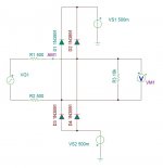
Much too big a diode. Try it with 1N914 or 1N4148. The capacitance of the big diode will degrade everything.
The voltages to clamp to are the supply rails of the input opamp. Most semis can handle as much at .7V beyond the rails on their inputs without damage.
I want to place the protection on output of mine tube mic preamp, not on input of a downstream line amp / computer card.
The tube preamp can potentially produce large Vout up to ~150V (Yes I've measured it with DMM while touched input tube grid to make BUZZZ), that is why I've took large diodes. I think if diode breaks it wont stop overflow. Am I right?
Though you said you want to place the protection in the preamp, you could solder diodes to the replaced/repaired soundcard inputs. There's +5V and -5V inside PCs you could use as clamp points (your VS1 and VS2 sources in your diagram).
Or you could rectify the heater supply (assuming you have a grounded 6.3V winding, or a pair of 3.15VAC's (usually from a 6.3VAC winding with a hum cancelling pot to create a phantom centertap). The 3.15VAC will give you about 4VDC and -4VDC for the diode clamp voltages (your VS1 and VS2 sources in your diagram). .
Or you could rectify the heater supply (assuming you have a grounded 6.3V winding, or a pair of 3.15VAC's (usually from a 6.3VAC winding with a hum cancelling pot to create a phantom centertap). The 3.15VAC will give you about 4VDC and -4VDC for the diode clamp voltages (your VS1 and VS2 sources in your diagram). .
That might work pretty well. A pair of LI button cells with reverse biases 1n4148's would have a life of about 10 years. bypass them with a 1-5 uF film cap. The leakage of an electrolytic would drain them. Its the cap that will absorb the overload. However if the source is strong enough it will attempt to fry the batteries.
@1Audio
Unfortunately LI cells are 3.2V.
Ideally 1.8V batteries are required.
Or, may be, they should be "aged" down to 1.8V?
Also I want to put an incandescent lamp there.
SPICE shows that 12V 0.5W should be enough.
What kind of lamps are there in those schematics you have posted?
Unfortunately LI cells are 3.2V.
Ideally 1.8V batteries are required.
Or, may be, they should be "aged" down to 1.8V?
Also I want to put an incandescent lamp there.
SPICE shows that 12V 0.5W should be enough.
What kind of lamps are there in those schematics you have posted?
Last edited:
Watch the peak voltage, not the RMS voltage. 1.8 will be hard. Check the input circuitry of most sound cards. It will handle 1.5 to 2 V rms. 2 * 1.414 = 2.828V peak.
@1Audio
Also I want to put an incandescent lamp there.
SPICE shows that 12V 0.5W should be enough.
What kind of lamps are there in those schematics you have posted?
Usually they are 120V/3W lamps and can handle the continuous output of a power amp with the input set to high gain. That's where the protection comes in.
Watch the peak voltage, not the RMS voltage. 1.8 will be hard. Check the input circuitry of most sound cards. It will handle 1.5 to 2 V rms. 2 * 1.414 = 2.828V peak.
I referred to "professional audio" voltages from here Line level - Wikipedia, the free encyclopedia for +4dBu or 1.228VRMS or +-1.736V or 3.472V p-p.
So protection should pass below +-1.8, that is why batteries should be 1.8V. am I right?
However "consumer audio" is like 4 times less.
Probably I should consider a 3-pos switch in protection. Like Consumer - Professional - No protection.
thanks for lamps info.
Those levels refer to operating levels, not peak levels. The peak can be as much as 20 dB higher. Most consumer stuff peaks at 2V RMS and the pro stuff can be higher than +24 dBm (12V)
From the Emu spec:
Hi-Z Line Input:
Input Impedance: 1Mohm
Max Level: +12dBV (14.2dBu)
Dynamic Range (A-weighted, 1kHz, min gain): 113dB
Signal-to-Noise Ratio (A-weighted, min gain): 113dB
THD+N (1kHz at -1dBFS, min gain): -101dB (.0009%) RMS).
+12 dBV = 4V RMS
That's why I suggested the Li batteries.
I understand that a tolerance to high V peaks can differ for different line amps. My point was to set a max output voltage of mic amp so it should be a little bit higher than max V of operating levels. It should not matter if a particular downstream line amp can tolerate 24V or 12V.
We should not send that to it because anyway distortions will be high. So my understanding is that if signal goes above +4Dbu we can cut it, even though a line amp can tolerate much more. Am I right?
We should not send that to it because anyway distortions will be high. So my understanding is that if signal goes above +4Dbu we can cut it, even though a line amp can tolerate much more. Am I right?
I guess it also depends on how you plan to use the micpre, only at home with a soundcard or in real professional studios? Their input level requirements are quite different. I think you have the GT Vipre manual, so take a look at its specs, which has the options for +30dBu (24.2Vrms) balaced output and -10dBu (0.244Vrms) un-bablanced output.
Currently output is unbalanced. I am thinking to add output transformer to make it balanced.
I am not sure about pro studio, but I can add +30dBu setting to output switch. It should be not too difficult. Though in this case the ref voltage +-25V wires should be add to umbilical PSU cable.
I am not familiar with pro studios, do they really often have equipment for +30dBu?
Or, may be, like in Vipre a Mute switch should be added, that switches between "mute" resistor 10KOhm and a downstream line amp?
How would you do?
What I've got reading this Line level - Wikipedia, the free encyclopedia and further links:
- there are two standard nominal levels: Pro Audio is +4dBu or +-1.736Vpk; Consumer Audio is -10dBV or +-0.447Vpk.
A capability of a particular line amp to tolerate voltages above these, is called Headroom. And this headroom is not covered by standards, some line amp can get more Vpk than another.
So, a "universal" line output protection should have basically two levels, Pro and Consumer. It should clip voltage to something like +- 1.9Vpk for Pro, and to +-0.5Vpk for Consumer, regardless if some line amp can get much more than nominal level standard prescribes.
I assume that all equipment should have some headroom that is why protection levels are slightly higher than standard nominal levels.
Am I right?
The problem with the 'power supplies' is that they have to withstand a serious load if you try 100 Volts into a 500 ohm resistor. I would think 3 series silicon diodes paralleled with 3 series diodes diodes reverse polarized and tied to ground would be better. The capacitance of the series diodes would nearly disappear being in series and being ground referenced would likely short out under a loud blast. If they shorted it would stop the recording but not blow up the next stage. 1N4148 can do 200 mA average and 1 A for 1 second (Fairchild data sheet) 4pF (remember they're in series) and 4nS reverse recovery. And they're cheap. That 'clamp' would allow 4 Vp-p which would be good for a soundcard input.
G²
G²
The diodes have a pretty coarse turn on curve and will introduce distortion. You need the supply so they can be reverse biased in normal operation.
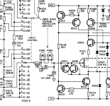
This problem is the same in any distortion analyzer. if you look at the schematics for the input attenuator you will see various implementations of this circuit. They have the same problem eexcept that the source may be a big poweramp with no current limiting.
Usually, after the input divider there is a resistor or lightbulb in series with the high impedance input. The clamping diodes are after the series current limiting resistor. Light bulbs are used because the lower resistance means lower noise and they increase in resistance as they heat up, further limiting the current.
Below is the implementation from the Amber 3501. You will see the back to back transistors from gate to source and then the diodes from the sources to the supply rails.
Its much harder to implement this in the source device.
Attachments
@Stratus46.
Yes, it is excellent idea because it is "self biased" - no need for batteries or additional PSU wires.
It is also easy to switch to Consumer level (just one diode) or extra headroom level (more than 3 diodes).
@1audio
Yes, it is excellent idea because it is "self biased" - no need for batteries or additional PSU wires.
It is also easy to switch to Consumer level (just one diode) or extra headroom level (more than 3 diodes).
@1audio
I tried in SPICE simulation with four 1N4148, it does not show significant additional distortion. Can diode be reverse biased by another diode(s)?The diodes have a pretty coarse turn on curve and will introduce distortion. You need the supply so they can be reverse biased in normal operation.
Last edited:
I am not familiar with pro studios, do they really often have equipment for +30dBu?
I'm not sure about +30dBu, but all of them have the ability to pad down the signal either with an external attenuator or on-board attenuator which is the first thing that gets set when a session starts. But it seems like you are not really planning to work in a studio, so a simple input clamp/limiter for the soundcard would do.
If you're going into a digital recorder soft clipping means nothing. You just want the hard clip of the diodes higher than the FS signal. Once you hit full scale the distortion goes through the roof anyway. You just want to not blow up the next stage, right?
G²
G²
- Status
- Not open for further replies.
- Home
- Amplifiers
- Tubes / Valves
- protection of downstream line amp