HI all,😛
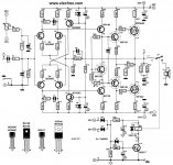
I am showing here for the second time the HexFET amp from Elektor for the following reasons-
Quoted from the previous help thread on this amp;
*connect a 1N4004 or similar and a 12V zener protection diodes to Gate - Source terminals
*A of zener1 to G of T12
K of zener1 to S of T12
A of zener2 to S of T13
K of zener2 to G of T13
Looking further at the circuit, both channels means S to VAS rail and D to mid-v (out). If the symbol used for the output was precise then to my understanding the suggested placement for the protection diodes would become -
A of zener1 to D of T12
K of zener1 to G of T12
A of zener2 to G of T13
K of zener2 to D of T13
Is this correct?
From the previous help thread there was a mention of using 6.8v, and 12v for the zeners. Was there a difference?
One constructor mentioned of replacing P2 I wonder what rating would that be...🙂 Sorry some links no longer exist from the previous thread can't view your modified versions🙁
Your guidance will surely clear things out for me....
Thanking you in advance😉
(sorry mooly, no can do, I guess your design will have to wait, lateral mosfets will only become available upon ordering in this place. I don't do this..too risky and most likely you'll get fake ones😡...always happen.)
I am showing here for the second time the HexFET amp from Elektor for the following reasons-
Quoted from the previous help thread on this amp;
*connect a 1N4004 or similar and a 12V zener protection diodes to Gate - Source terminals
*A of zener1 to G of T12
K of zener1 to S of T12
A of zener2 to S of T13
K of zener2 to G of T13
Looking further at the circuit, both channels means S to VAS rail and D to mid-v (out). If the symbol used for the output was precise then to my understanding the suggested placement for the protection diodes would become -
A of zener1 to D of T12
K of zener1 to G of T12
A of zener2 to G of T13
K of zener2 to D of T13
Is this correct?
From the previous help thread there was a mention of using 6.8v, and 12v for the zeners. Was there a difference?
One constructor mentioned of replacing P2 I wonder what rating would that be...🙂 Sorry some links no longer exist from the previous thread can't view your modified versions🙁
Your guidance will surely clear things out for me....
Thanking you in advance😉
(sorry mooly,
no can do, I guess your design will have to wait, lateral mosfets will only become available upon ordering in this place. I don't do this..too risky and most likely you'll get fake ones😡...always happen.)Attachments
hi abeeter, where you located in PH?
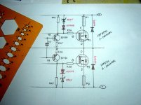
refer to the attached schemetics on how to connect the protection diodes. You can also try this schematic which uses N channel mosfets which are abundant here in PH.
you can purchase lateral Mosfet in RAON in manila but in higher price compared to IRF's.
refer to the attached schemetics on how to connect the protection diodes. You can also try this schematic which uses N channel mosfets which are abundant here in PH.
you can purchase lateral Mosfet in RAON in manila but in higher price compared to IRF's.
Attachments
![quasicomp_2[1].gif](/community/data/attachments/183/183018-c5b1692c6ee1fc21df1622d477e337eb.jpg?hash=xbFpLG7h_C)
Easternmost in Region V, I work here in a geothermal facility, fact is Kapampangan runs my blood😉 Mekeni ku naman...surprised? I live here na😛
I'm still confused 'bout the pin assignment of the drain & source . Upon encountering various mosFET circuit, to most of them the source was tapped to mid-voltage(out) and the drain to voltage supply. The gate is always fixed. This one here was different though...
 I had the parts, well at least for one channel (no turning back eh😀). I'm currently doing a revision of the pcb, that is why I need to figure-out the proper circuit for the protection diodes.
Thanks & Regards
I'm still confused 'bout the pin assignment of the drain & source
. Upon encountering various mosFET circuit, to most of them the source was tapped to mid-voltage(out) and the drain to voltage supply. The gate is always fixed. This one here was different though... I had the parts, well at least for one channel (no turning back eh😀). I'm currently doing a revision of the pcb, that is why I need to figure-out the proper circuit for the protection diodes.Thanks & Regards
So you don't blow the gates when clipping into a low impedance load.
A small resistor needs to be inserted between the collectors of the driver transistors and the diode strings
A small resistor needs to be inserted between the collectors of the driver transistors and the diode strings
I am not trying to discourage you but I hope you are not expecting it to give you 120w (not even 60w) with a power rail of +-35v and a pair of outputs like that.
You're quite right both collectors of the driver transistors were tied to VAS rail, will it do if I move the diode string and place it after the resistors at the gates?So you don't blow the gates when clipping into a low impedance load.
A small resistor needs to be inserted between the collectors of the driver transistors and the diode strings
Hi,
Yes. You don`t need the external diodes across drain and source.will it do if I move the diode string and place it after the resistors at the gates?
to meanman,🙂
from the previous help thread on this amp a forum member named ricknl posted the following-
In the July-Aug 2002 Elektor mag, a revision to get better stability from both versions (mentioned the next higher power brother) was published.
Place 27nF parallel to R31
Place a resistor of 20K between collector of T8 & ground
Place a resistor of 20K between collector of T9 & ground
Replace R20 by 1K8
Replace R17 & R18 by 390 ohms
Replace R3 & R4 by 33 ohms
According to Elektor this should improve the stability & the performance of the amp.😉
If someone though can confirm, that these mod work perfectly right, then it would be a relief😀
to bigpanda,🙂
Yep I am aware of it, so long that it sounds alright though, I only had 150watts pair of loudspeakers for this amp.
Before you do all the mods try by adding 220p caps between the collector and base of T10-T11 and T8-T9 use a Mica a tip from Hugh Dean of the Famous Aksa amps(Aspen)http://www.diyaudio.com/forums/solid-state/27200-hexfet-power-amplifier.htmlAlso look here http://www.diyaudio.com/forums/solid-state/112426-hexfet-amp-please-help-me-fix-6.html post56
Last edited:
Hi Junm,
Can you kindly show us the link to your 'sample schematic'. Just want to have a closer look at it.
Tks
Can you kindly show us the link to your 'sample schematic'. Just want to have a closer look at it.
Tks
meanman1964,
that's certainly true. Have you built it?
I've one original Hexfet with nothing changed but planning to add those caps.I also have 4 pairs of the IGBT versions only one(1 channel) is playing stable without any mods.By one IGBT stereo version I did the Eddelarue mod http://www.diyaudio.com/forums/solid-state/112426-hexfet-amp-please-help-me-fix-2.html but still need to be tested.
There are many people saying take another amp design with fets but I can't explane but they have me in a grip I need them to play stable and they will be no matter what.
Last edited:

With all of the complications that this amp had gone, perhaps the suggested caps (220pf/100pf) might do the trick 😉 It looks like the suggested mod from Elektor was not helping at all eh 
Well, I'll take my chances then build the thing and see what will happen 😀
Thank you guys for the help🙂
-Pls. disregard my own interpretation of the protection diode in post #1, my failings upon seeing the schematic of the quasi (posted by JunM) I get the idea.
Well, I'll take my chances then build the thing and see what will happen 😀
Thank you guys for the help🙂
-Pls. disregard my own interpretation of the protection diode in post #1, my failings
upon seeing the schematic of the quasi (posted by JunM) I get the idea.With all of the complications that this amp had gone, perhaps the suggested caps (220pf/100pf) might do the trick 😉 It looks like the suggested mod from Elektor was not helping at all eh
Well, I'll take my chances then build the thing and see what will happen 😀
Thank you guys for the help🙂
-Pls. disregard my own interpretation of the protection diode in post #1, my failings
Soon gonna try it myself keep you all informed
meanman,
How to Build a 100 Watt MOSFET Amplifier Circuit? Simple Design Explored
check this link, perhaps the designer of this one has seen the shortcomings of the Elektor hexfet, take notice of the caps at the drivers and the source resistors only, that this one uses lateral mosfet instead, similar design same power requirements🙂
- Status
- Not open for further replies.
- Home
- Amplifiers
- Solid State
- PROTECTION DIODE on HexFET Amp, HELP!