Hi everyone,
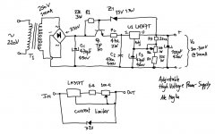
I built a variable high voltage power supply to be used whilst breadboarding some valve preamps and SET projects I'm currently working on. The design is based on the circuit proposed by Jones in "Valve Amplifiers" and I have also added a current limiter also using an LM317.
The power supply works perfectly fine, nothing to complain about, however I have had some high current spikes / shorts whilst breadboarding some circuits and couldn't prevent blowing the zener, the transistor and also the LM317 of the power supply. I hoped that the current limiter would help me here, but no.
Any suggestions to protect the power supply from short circuits other than a simple quick blow fuse?
This is my first post, so sorry if I post this in the wrong place and many thanks for the help.
Cheers,
Ale
Attachments
LM317 isn't really suitable for HV circuits, even though you might manage to obey its 40V (or thereabouts) maximum In<->Out voltage. There are some higher voltage variants avaliable, such as TL783 etc.
If, for example, your tube supply has to charge a significant capacitance, it is bound to exceed the specifications while in transition from one state (off) to the other (on). You need to minimize such excursions outside permitted maximum ratings range or use more resilient components (yes, tubes tend to work extremely well as high voltage linear regulation devices 😉 ).
If, for example, your tube supply has to charge a significant capacitance, it is bound to exceed the specifications while in transition from one state (off) to the other (on). You need to minimize such excursions outside permitted maximum ratings range or use more resilient components (yes, tubes tend to work extremely well as high voltage linear regulation devices 😉 ).
I have built Maida-style regulators that have survived arcs to ground on the output. A couple of things that I do differently:
1. I follow the circuit in the app note written by Maida pretty closely. I use a mosfet instead of a darlington.
2. I leave off the capacitor at the input of the LM317. I think that cap might be storing the energy that is blowing out your semiconductors. I think that Jones mentions this in his book.
3. I do not put significant capacitance at the output of the regulator. It is not necessary and makes startup difficult on the regulator. I have the RC snubber like in the app note.
With C3 in there, you need a protection diode from output to adjust pins. And you should have 4-5 ohms in series with the 100u output cap.
There are fast blow fuses, and then there are Picofuses. These are said to be fast enough to protect a transistor's junction. They are axial lead fuses the size of a ¼ watt resistor. A quick connect system like Fahnestock clips would be helpful.Any suggestions to protect the power supply from short circuits other than a simple quick blow fuse?
Last edited:
My first thought was to remove C3 too. Looked up the datasheet and C3 is for extra ripple rejection wich is not a bad idea but if you use it and high output capacitance then you need protection diodes. Datasheet shows 1N4002's, one connected cathode to IN and anode to OUT and one connected cathode to OUT and anode to ADJ. That's where I would start. Also a 1N4002 anode to emitter and cathode to base of Q1 and a 1N4004 anode to emitter and cathode to collector of Q1 would not hurt.
Last edited:
mogliaa,
Take a look here:
http://www.diyaudio.com/forums/tubes-valves/174667-has-anyone-used-regulator.html
I built the one in the first post it is similar to yours.
Regards
M. Gregg
Take a look here:
http://www.diyaudio.com/forums/tubes-valves/174667-has-anyone-used-regulator.html
I built the one in the first post it is similar to yours.
Regards
M. Gregg
Last edited:
Hi everyone,
I built a variable high voltage power supply to be used whilst breadboarding some valve preamps and SET projects I'm currently working on. The design is based on the circuit proposed by Jones in "Valve Amplifiers" and I have also added a current limiter also using an LM317.
I gave up on that method. I now use a simple HT power supply with CRC filter controlled by a variac auto-transformer. I can get from a few volts to 400V just by turning a knob. The supply is robust enough the all I need for protection is a fuse.
Here is a tube regulator that can not so easily been damaged.
It is easy to build, as you can see.
It is easy to build, as you can see.
An externally hosted image should be here but it was not working when we last tested it.
An externally hosted image should be here but it was not working when we last tested it.
I too am a believer that the LM317 should not be used in a high voltage lab supply.
Here is a full tutorial how one might be designed with valves: Tube Based Voltage Regulators - Part 1
Here are some other links that might be usefull if you chose to use tubes instead.
6L6 + 12AX7a
EL34 + EC92 (ECC81)
6GV8 / ECL85
EL84 + EF184
Here is a full tutorial how one might be designed with valves: Tube Based Voltage Regulators - Part 1
Here are some other links that might be usefull if you chose to use tubes instead.
6L6 + 12AX7a
EL34 + EC92 (ECC81)
6GV8 / ECL85
EL84 + EF184
With C3 in there, you need a protection diode from output to adjust pins. And you should have 4-5 ohms in series with the 100u output cap.
I have built Maida-style regulators that have survived arcs to ground on the output. A couple of things that I do differently:
1. I follow the circuit in the app note written by Maida pretty closely. I use a mosfet instead of a darlington.
2. I leave off the capacitor at the input of the LM317. I think that cap might be storing the energy that is blowing out your semiconductors. I think that Jones mentions this in his book.
3. I do not put significant capacitance at the output of the regulator. It is not necessary and makes startup difficult on the regulator. I have the RC snubber like in the app note.
My first thought was to remove C3 too. Looked up the datasheet and C3 is for extra ripple rejection wich is not a bad idea but if you use it and high output capacitance then you need protection diodes. Datasheet shows 1N4002's, one connected cathode to IN and anode to OUT and one connected cathode to OUT and anode to ADJ. That's where I would start. Also a 1N4002 anode to emitter and cathode to base of Q1 and a 1N4004 anode to emitter and cathode to collector of Q1 would not hurt.
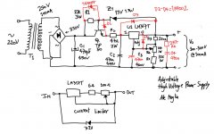
Thanks everyone for your suggestion and tips. I will give it a go and try the protection diodes and removing the output filtering cap and replacing it with the RC network suggested - see attached diagram
I will try the above as I have the circuit built on a PCB before trying the MAIDA one with the mosfet.....
Cheers,
Ale
Attachments
One more thing- you probably don't need C2 and eliminating it will help the reliability.
Ok, will try that as well, thanks!
Ale
- Status
- Not open for further replies.
- Home
- Amplifiers
- Power Supplies
- Protecting a valve variable LM317 power supply