Hi All.
I have recently completed Rod's P3A amplifier. Used his PCB for it.
I would like to add some DC protection for my speakers.
Now I have built those uPc1237 Ic circuits for some amplifiers. They work great, and the added turn-on delay is nice.
But, I was wondering what advantages/ disadvantages would a simple electrolytic capacitor in series to the speaker have.
Why isn't it done with split supply amps??
Does it affect the sound?
Erm...Split supplies were developed precisely to eliminate the output capacitor. You can do as you please with adding a capacitor - even taking the NFB point to the output side to include it in the loop but there is now little point in having dual rails.
There are dozens of threads here about capacitors, output capacitors and what's bad about them. Some folks would eliminate all reactive components from amplifiers if it were possible. If you want to start yet another unending thread about capacitors in amplifiers you will be going about it the right way - Just watch this space. 🙄
There are dozens of threads here about capacitors, output capacitors and what's bad about them. Some folks would eliminate all reactive components from amplifiers if it were possible. If you want to start yet another unending thread about capacitors in amplifiers you will be going about it the right way - Just watch this space. 🙄
"Why isn't it done with split supply amps?" Because you would have to use a non polarized capacitor because you would not know if the amp failed and put out a positive or negative voltage. These are almost impossible to find in the thousands of uF size and would be very expensive. "Does it affect the sound? " Yes, all signal coupling capacitors add distortion.
You would need a bi-polar cap so that means two caps back to back of twice the value you want the equivalent "single" cap to be ... bulky.
(Ian mentions moving the feedback take off point to the other side of the cap to include and correct the "bad" effects of the cap... if designed in from the start then yes, a good idea, but otherwise what about the DC conditions 😀))
(Ian mentions moving the feedback take off point to the other side of the cap to include and correct the "bad" effects of the cap... if designed in from the start then yes, a good idea, but otherwise what about the DC conditions 😀))
Yes, I see the loophole. Apologies...... but otherwise what about the DC conditions 😀))
I should have said "as there is now no point in having split rails." or clearer.
The Quad floating ground idea gives the same DC protection as a series cap, but is still a DC coupled output as far as the amp and speaker is concerned. However, I suppose that if you have 100,000uF of PSU capacitance it wouldn't help all that much. In the days when 4700uF was enough for a 100W amp, it was a very elegant idea.
http://www.diyaudio.com/forums/powe...und-power-amp-applications-3.html#post2326158
http://www.diyaudio.com/forums/powe...und-power-amp-applications-3.html#post2326158
Member
Joined 2009
Paid Member
You could use a single cap on the output of a split-rail amplifier. As far as I can see you risk it exploding if the amp fails and the capacitor is then reversed biassed. But so what.
I have found a single cap not to affect the sound of a split rail amp except with very careful listening. Use a large value cap so that there is very little a.c. voltage across it to minimize distortion. Use a good quality cap such as Nichicon gold.
The only other issue I'd worry about is that electrolytics are designed to have some d.c. across them, it helps keep their internal structure properly 'formed'. You could achieve this by mis-balancing the amplifier to produce a little intentional d.c. at the output, but this might affect sonics depending on how it's implemented.
I don't know if the impact on sonics is too critical - worrying about your speakers is likely to impact your enjoyment of the music more. The smell of a burnt out voice coil is guaranteed to spoil your day !
Last edited:
I have a single supply amp, the ST120 with djoffe bias mod, with an input and an output capacitor(3300 @ 80v). On my Peavey SP2-XP speakers, it sounds just like the CS800s split supply amp with no input or output capacitors, at 1.5 Vpp level. Both sound better than the "legendary" stock ST70 tube amp with new caps and output tubes. A new CS600s was $999 at the local store 2 years ago, so decent protection circuits like it has, are not cheap. I paid about $200 for the CS800s with several problems, like tripping the breaker sometimes when I turn it on (1998 main caps) and burnt up input resistors.(probably somebody plugged a hot guitar amp output in it and burned them).
I tried putting 10000 uf back to back electrolytic caps between the speakers and the output transistors on the CS800s. It sounded funny on top octave Steinway piano, which I know what it is supposed to sound like. (I've got one installed between the speaker stands). It also sounded funny on tinkly bells and brush cymbals. I'll have to rely on the speaker disconnect relays and the overcurrent detection current transformers of the CS800s to protect the speakers. I don't like funny sounds.
I've just spent over a month fiddling with the Peavey PV-1.3k split supply amp trying to install something better for DC protection than the SCR crowbar that melts the lands on the PWB instead of tripping the breaker and protecting the speakers. The detection circuit is working, but the lands of the PWB are not tough enough to carry 10000 uf of energy @ 85 V. I think it would be easier to build a couple of channels of single supply amp- like the MJR7-4 or G amp than what I am doing. Have just bought the parts to try the G amp. Speaker disconnect relays are also notorious for sounding funny, particularly after several years of dirt gets on them. Also, 8 to a dozen parts have to work right for the speaker disconnect to work. The number of speakers at the local musician's consignment shop witn new cheap bass drivers, and the number of amps with shiny new output transistors, is evidence that blown amps blowing speakers is not a rare phenomenon.
Last edited:
Member
Joined 2009
Paid Member
I have a hard time trusting output relays to protect speakers in off-the-shelf amplifiers because they don't always implement it properly. In most cases the relays are there to control turn-on and turn-off noises rather than guarantee your bass drivers will survive an output stage failure. The issue I've seen is mostly that the relays are underated for use with inductive loads, and there are very few relays that are adequately rated and available for purchase so it's unlikely a commercial amp has used one with sufficient rating unless it's a low power amplifier to start with. Secondly, the relay needs to be a two-way relay, the speaker terminal needs to switch from being connected to the output of the amplifier, to being connected to ground. This ensures that any d.c. arcing is quenched quickly when the relay tries to disconnect the inductive load it's connected to.
I have a project on the bench which is a commercial amp with inadequate output relays. I am considering adding additional speaker protection.
I have a project on the bench which is a commercial amp with inadequate output relays. I am considering adding additional speaker protection.
When taking the sonic influence in mind, I actually would prefer a speaker protection based on the u1237, or similar, wich uses an relay to connect the speakers.
The alternative with capasitors would require four capacitors with a value of each the double of the PSUs total capasitance to give a neglectiable influense to the properties of the amp. This as we will need to put two in series, aka Bipolar, not to decrease theese properties.
The alternative with capasitors would require four capacitors with a value of each the double of the PSUs total capasitance to give a neglectiable influense to the properties of the amp. This as we will need to put two in series, aka Bipolar, not to decrease theese properties.
A single power rail starts to look more attractive now, doesn't it. 😉......would require four capacitors with a value of each the double of the PSUs total capasitance to give a neglectiable influense to the properties of the amp. This as we will need to put two in series, aka Bipolar, not to decrease theese properties.
Thanx for all the input guys.
Just a question, can someone confirm the statement that capacitors need dc on them at all times??
Just a question, can someone confirm the statement that capacitors need dc on them at all times??
They don't need DC on them, in fact many signal stages use electroylitics that have essentially 0.00 volts across them.
Member
Joined 2009
Paid Member
many signal stages use electroylitics that have essentially 0.00 volts across them.
I have been looking inside my Pioneer HT amp (non functional) and it has gazillions of cheap electrolytics in the signal path 😱
I too am convinced that a speaker can NOT be protected by just a relay. Relays can arc and weld shut. It is entirely possible to have the high power rails for the outputs switched. Trench-type mosfets happen to have a very low Rds on. Although these devices are not suitable for analog amplification they are very good as switches, and they are cheap.🙂 A Trench fet may have a Rds on <60mOhm. In my latest amp I use relays in combination with solid state switched power rails, controled by the logic circuitry that after about 3 seconds shuts down the output stage power rails in the event of DC detected at the output. I used a variation of Rod's DC detection circuit. Also the power rails are fused, and if a fuse were to break, in the event of a prolonged short, the power rails shut down within ~0.5sec.😉 I did a test, I shorted the output to one of the rails. This will typically destroy any power amp of similar construction. The oposite fuse blew as expected, a half second duration of DC went to the speaker and then it switched off.
Last edited:
At what voltage a speaker is in danger?
Some protections to trigger +-0.6V, others +-10V, etc ... I am a little confused!
Some protections to trigger +-0.6V, others +-10V, etc ... I am a little confused!
Do a little calculation assuming say 6 ohms DC resistance for the voice coil.
If its a large speaker then it will "withstand" several volts. 10 volts equates to around 16 watts. Thats probably survivable for some time until the coil heats enough to start melting the glue that bonds it to the cone. A small speaker wouldn't survive for so long. 16 watts is more than you think. I have an 18 watt soldering iron.
Protection circuits should probably trigger at around a couple of volts of either polarity as a maximum ball park figure.
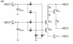
Here is a diagram which I think is interesting because there is no need to supply (relay kicks in at + / - 10V).
By changing the value of a relay 6V zener, it must be down to about + / - 5V.
What do you think of this scheme?
http://www.schema-electronique.net/2010/06/une-protection-pour-haut-parleurs.html
Regards!
By changing the value of a relay 6V zener, it must be down to about + / - 5V.
What do you think of this scheme?
http://www.schema-electronique.net/2010/06/une-protection-pour-haut-parleurs.html
Regards!
Speed of release could be a problem. A speaker cone would hit the end stops in milliseconds and the damage is done/can be done. Voice coils actually set on fire when connected across high DC... believe me... I've done this (deliberately) dozens of times. The relay would have to break (and continue to break) a substantial arc that DC and high inductive load would cause. You need a substantial relay for that.
- Status
- Not open for further replies.
- Home
- Amplifiers
- Solid State
- Protecting a speaker from DC