Look at it this way. Put the CL-140 in series with the rectifier's cathode, between pin 8 and the first filter cap. It does the same thing, and is effectively in the same place electrically. If you are building your amp, you can do it either way. I put it in series with the HV CT since it was being added to an existing design and this was the easiest way to accomplish the task.
As stated the charging current flows in short bursts at the crest of each sine wave.....except at turn on. Here huge currents flow nearly continuously from the time the rectifier starts conducting until a steady state condition is reached. During that time it helps to have added resistance to blunt the large currents, and especially a large resistance that gets smaller as it heats up.
If the amp is designed and built correctly there should be separate charging and discharging loops intersecting only at the filter caps. All grounds in the power supply and the amp should meet at the negative side of the caps which should ideally be right next to each other with their negative terminals connected together. Any resistance added in the charging loop will NOT affect the ESR of the filter caps, only the loop resistance of the charging circuit.
Doesn't manipulating the ground loop introduce new challenges wrt earthing the audio chain? If the DC-offset is a couple of volts, so is the ground return of the audio signal.
I was looking for a thermistor inrush current protector myself, although in the HT, perhaps two in series can do the job. Mind the max capacity specification...
https://www.amphenol-sensors.com/en...sh-cl-series-datasheet/download?Itemid=8482 '
I was looking for a thermistor inrush current protector myself, although in the HT, perhaps two in series can do the job. Mind the max capacity specification...
https://www.amphenol-sensors.com/en...sh-cl-series-datasheet/download?Itemid=8482 '
Last edited:
windcrest, a standard glass 250vac in the ac rectifier loop is typically fine for valve amps using valve diodes, as secondary voltages typically don't go above 500v, and load current is typically below a few hundred mA. If you are DIYing significantly higher voltage or current levels then you need to go to another level of appreciating protection and safety imho.
Doesn't manipulating the ground loop introduce new challenges
It is important to understand that there are several current loops in an audio amplifier. Under most circumstances they should each meet at exactly one point, the negative terminal of the largest filter capacitor, often called the star ground point.
The current loop that charges the filter caps (current fed into the power supply) MUST not interact with any of the other loops in the amp, especially those associated with low level signals.
The amplifiers main discharge loop (current drawn from the power supply) should be from the positive terminal of the main filter cap through the OPT, then the output tube(S), and from the output tube's cathode back to the negative terminal of the main filter cap.
The driver and any other low level stages should also have similar independent loops.
We are NOT changing anything grounding wise, or otherwise in the audio chain, only adding a time variable resistance in series with the power transformer's HV secondary. The audio chain is untouched, the only change is in the current path that charges the amplifier's filter caps. This is the dirtiest current loop in the entire amplifier, and any added resistance can only help reduce the line frequency harmonics that are generated by the short duration pulses of diode conduction, by reducing the peak current.
This resistance can be added in one of three places with the same effective result.
It can be in the HV winding's center tap. Note that the actual ground point for the entire amp is AT THE NEGATIVE TERMINALS OF BOTH FILTER CAPS, and NOT at the junction of the transformer CT and the CL140. Yes this will raise the AC voltage seen inside the transformer by a few volts or so WRT ground, but it runs in the many hundreds of volts already, so it doesn't matter. Ham radio builders, myself, and a few other audio amp builders working with kilovolt designs often put the filter choke and first filter cap here too since it reduces it's voltage rating requirement. Done right, it doesn't mess with any of the audio path grounds either.
The same CL140 can be split in half (2 X the resistance) and placed in each plate lead of the rectifier tube. This is where the old textbooks and tube manuals show the adding of additional resistance to meet the peak current specs of the rectifier tube. This is not a real option here since the CL140 is already the smallest available part and most of our amps are running it below it's suggested minimum current.....feeding it half the (time averaged) current will only insure that it never reaches operating temperature.
The CL140 can be installed in the wire leading from pin 8 of the rectifier tube to the first filter cap. This is exactly where the manufacturer's spec sheet shows it being installed. If you are still convinced that the grounding will be messed up, put the CL140 here.....note that the 5 volt heater winding still gets connected directly to the tube.
Also a big thanks! At 65 I only have a few decades left to really learn a hobby I last enjoyed as a kid, knowing nothing 50 years ago except how to hook up things from a schematic. Eventually, bit by bit, things start to make sense now.
Indeed a great read, many thanks to the experienced people here for the information and explanation
At 65 I only have a few decades left to really learn a hobby I last enjoyed as a kid, knowing nothing 50 years ago except how to hook up things from a schematic.
I'm 66 and I started a bit more than 50 years ago. Good schematics were not easy to find back then. There were some old books in the library, the usual electronics magazines, and a ham radio neighbor who wound up being an engineer at a local radio station (and his books), but most of my schematics were obtained by taking something apart and tracing it.
I made guitar amps at a young age starting with a hand traced schematic of an old Fender Champ. Did I have a clue what I was doing? NO, but that didn't stop me. Questions like why does my amp really rock with a small output tube (6BQ6) but isn't loud, the tube glows red, and the OPT smokes when I stick a bigger tube in (6DQ6) remained unanswered. Of course it wasn't until high school electronics class that I learned about impedance, bias, and load lines......then the bulb began to glow.
At age 20 I got a job in a local Motorola plant, and silicon was free just by filling out a sample request, so my world was mostly solid state from 1974 to about 1988. I made clones of all the SWTPC Tigers and their MC6800 computer, but I traded my first car for an old Scott tube stereo in the late 80's, which soon kicked the Carver / Phase Linear system out of the stereo rack and the seeds for Tubelab were planted.
I'm 66 and I started a bit more than 50 years ago.
Thanks for your backstory. As a kid I took apart every radio and TV all my uncles decided to trash or expected me to fix for them. Collected parts galore. My dad would put the picture tube in a garbage can, cover it, then let me shoot the can with his rifle before he'd let me cannibalize a set though. Life happened between then and now. But as I enter semi-retirement my wife said what do you really want to do with your days if you retire while I', watching the grand kids? I said to finally understand how tube circuits work. After a career developing embedded systems and plant sensors and servos, and now developing autonomous trucks and self-diagnosing diesel engines... all I want to do is grow my tube bench and have the satisfaction of making a few things from scratch even chassis fabrication from raw metal stock.
After a career developing embedded systems
I spent 41 years of my life in the south Florida Motorola plants developing all sorts of tech, but mostly two way radios and cell phones.
put the picture tube in a garbage can, cover it, then let me shoot the can with his rifle
We would take old TV sets out to the edge of the Everglades, pile them up, and shoot them. Game warden came to investigate once.....we let him shoot one too. My first real paying job was in a TV repair shop. Plenty of dead TV's there too.
As a kid with minimal funds I shopped for parts at the local trash dump. Rip open an old TV, radio or HiFi set, take the tubes, transformers, and whatever components you could get, leave the rest behind.
i am 66 too like tubelab and i started in electronics at age 14.....silicon diodes are dirth cheap that i buy them by the hundreds nowadays...
I spent 41 years of my life in the south Florida Motorola plants developing all sorts of tech, but mostly two way radios and cell phones.
We would take old TV sets out to the edge of the Everglades, pile them up, and shoot them. Game warden came to investigate once.....we let him shoot one too. My first real paying job was in a TV repair shop. Plenty of dead TV's there too.
As a kid with minimal funds I shopped for parts at the local trash dump. Rip open an old TV, radio or HiFi set, take the tubes, transformers, and whatever components you could get, leave the rest behind.
Here in Philadelphia, it wasn't wise to go shootin' up picture tubes......LOL!
At the repair shop we just gave the tip of the necks a swat with a hammer to release the vacuum, and busted them up for trash.
Some, we recycled back to Zenith...
Because in 1994 they sold a huge batch of 25 inch sets with mexico-made tubes that shorted out - frying the chassis as well.
Tons of recalled sets we had to fix.
This then helped to bankrupt the company, at which point LG bought them out to save them.
LG used to be Goldstar, then Lucky Goldstar (LG).
Today, any Zenith branded product is actually LG.
Doesn't manipulating the ground loop introduce new challenges wrt earthing the audio chain? If the DC-offset is a couple of volts, so is the ground return of the audio signal.
We are NOT changing anything grounding wise, or otherwise in the audio chain... Yes this will raise the AC voltage seen inside the transformer by a few volts or so WRT ground, but it runs in the many hundreds of volts already, so it doesn't matter.
Got it. The only DC-offset wil be in the secundary of the power transformer, not in the ground.
Attachments
Thanks for your backstory. As a kid I took apart every radio and TV all my uncles decided to trash or expected me to fix for them. Collected parts galore. My dad would put the picture tube in a garbage can, cover it, then let me shoot the can with his rifle before he'd let me cannibalize a set though. Life happened between then and now. But as I enter semi-retirement my wife said what do you really want to do with your days if you retire while I', watching the grand kids? I said to finally understand how tube circuits work. After a career developing embedded systems and plant sensors and servos, and now developing autonomous trucks and self-diagnosing diesel engines... all I want to do is grow my tube bench and have the satisfaction of making a few things from scratch even chassis fabrication from raw metal stock.
We would take old TV sets out to the edge of the Everglades, pile them up, and shoot them. Game warden came to investigate once.....we let him shoot one too. My first real paying job was in a TV repair shop. Plenty of dead TV's there too.
As a kid with minimal funds I shopped for parts at the local trash dump. Rip open an old TV, radio or HiFi set, take the tubes, transformers, and whatever components you could get, leave the rest behind.
My experiences are very similar, with the exception of that shooting,
as rifles aren't that common over here. Most probably due to the lack of any Wild West heritage 😀.
Best regards!
I'm 41, and we used to play hammer toss with old TV sets in the trash... It's amazing how strong the front glass of a 25" CRT really is! We also used to get small electrolytic caps, wire them to a power cord, and plug them in to make "electric cherry bombs" 😛
Got it. The only DC-offset wil be in the secundary of the power transformer, not in the ground.
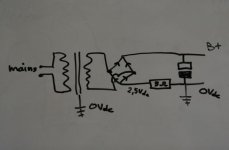
And from that schematic it's easy to see that the CL140 can be in either the positive leg of the bridge as in the data sheet, or the negative lead as you have drawn. Either way the bridge / transformer "source" and the CL140 are in series.
It's amazing how strong the front glass of a 25" CRT really is!
Yes, a direct shot to the face of a TV set with a high powered rifle will often go straight through the TV without much fanfare except for the hissing sound as it's vacuum is lost. A rifled slug from a 12 Gauge shotgun is a different story, but the best results were obtained with those plastic cased 19 inch B&W TV's from the 70's that had the 120 degree CRT. When shot from the side such that the CRT is hit where the face meets the bell, there is nothing left of the entire set that's bigger than a few inches. These sets had no chassis, only a PC board and a CRT. The biggest items left after the blast were the tuner, the yoke and maybe parts of the flyback.
"electric cherry bombs"
I bought a box of several hundred 470 uF 50 volt caps at a hamfest back in the early 70's. They turned out to be rather useless as capacitors due to their high ESR, but made decent firecrackers on the end of a 100 foot extension cord. A handful in the microwave oven made a good mess too.
The best "legal" big bang can be made with those 1 gallon Gatorade or juice bottles that are made of thick plastic. I drilled a hole in the center of the cap and epoxied a quick disconnect air fitting into the hole. Screw cap on bottle, connect long air hose to fitting, get far away, turn air compressor up to max pressure (mine hits 125 PSI) and wait for it to fill its tank, then plug hose into compressor, about 1 second later....BANG. The resulting bang is loud enough to draw a police response, but is technically not illegal in the USA......some angry cops don't understand this though.
125 PSI is not enough to detonate a 2 liter soda bottle, so I don't know how loud they are.....Ocean Spray cranberry juice and Gatorade bottled are very loud, some others just split at the seam.
In the US any bang that is created by a "chemical reaction" including rapid oxidation is considered a "destructive device" and mere possession of such is a felony in most jurisdictions....this includes the Draino and pool acid bombs we made as kids and ALL home made fireworks.
The Televisions were complete, and solid state. We'd just find one out to the curb, get out a hammer, and see who could break it from 20 feet away. More often than not, the hammer would just bounce off the glass! My friends once actually tripped the 100A main (on a 15A branch circuit!) trying to blow up a 10,000uF/25V cap
- Status
- Not open for further replies.
- Home
- Amplifiers
- Tubes / Valves
- Pros/Cons of fast recovery backup diodes on rectifier tube?