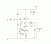
I posted this opinion in another thread:
http://www.diyaudio.com/forums/showthread.php?s=&threadid=6291
"I don't quite get the benefit of cascoding the Q3 current source with Q2; the output conductance of the current source shouldn't really matter because you have a 1K resistor and the load effectively shunting it anyway, and the cascode eats into the available voltage headroom before clipping."
Basically I think it is overkill, with the disadvantage of reduced headroom.
I would also wonder where are you going to get 3.5 V LEDs. They would have to be blue or white ones I'd think. Might it not be better to design for a green LED and reduce the 12 Ohm resistor accordingly?
-- mirlo
Well, it's interesting.🙄 I would much prefer not to use cascoded transistors like that, keeping as many junctions out of this as possible. And I'll bet it doesn't regulate any better than an ordianary dual transistor CCS, like is used in some of Slone's designs. I wouldn't use it.
ordinary dual transistor CCS
By this I assume you mean: use one transistor to sense the current in a resistor between its base and emitter and use its collector to drive the base of the second transistor [that actually passes the current.]
That is probably a better regulator, and also has more headroom than thie cascode.
But there is a possible advantage to the LED biasing. It may be possible to select an LED such that, its forward voltage will have similar temperature behavior to the Vbe of the BJT. Both junctions will have negative temperature coefficients of about 2 mV/K. The two transistor current source suffers from the negative tempco.
Yes, that's exactly what I mean.
Intersting thought with the LEDs (and here some people think LED=bad sound🙄 ). Might be worth some expirimenting.
Intersting thought with the LEDs (and here some people think LED=bad sound🙄 ). Might be worth some expirimenting.
I have standardized on using very large emitter (source) resistor to increase the compliance of a current source. I would think that this approach migh also benefit you in your application. So instead of dropping 3.5V or so on each leg, drop 7 volts or so over the sense resistor. I have at times dropped 20V and this is very effective ...
Petter
Petter
- Status
- Not open for further replies.
- Home
- Amplifiers
- Solid State
- Pro's and con's of CCS circuit.

