Have a look at post #10 which shows a 9.2VAC transformer (± 13V peak) that needs a snubber. (In my opinion)On low voltage stuff I have never needed a snubber.
This actually brings up an issue that should be mentioned: how does one determine if a snubber is "needed" or not? In my opinion, the waveform Mark refers to needs snubbing. There is clearly some ringing at a frequency much greater than the fundamental, as a result of strays. Careful and correct tuning of values can effectively remove the ringing, at least soften it to a great degree.
Another may connect a speaker to their amp, and not hear any hum/buzz/noise, and conclude that snubbing is "not needed". Even though the waveform shown may in fact exist in the amp. Then there are potentially any number of qualifications in between these two positions that a user may define to determine the need for snubbing.
It really comes down to how robust of a design do you want to build. It is certainly possible that ringing in a LV supply may be benign to the performance of a design. It is also possible the same ringing could radiate inside a chassis and couple to other circuits. Of the many issues that can be troublesome to a DIY build, I have taken the approach of building each block as robustly as possible within the cost target. A cheap RC has never proven to break the bank, and yet it removes one variable that I will need to consider when troubleshooting ghosts in the machine that I just finished building.
It's a philosophy; you must decide how important it is to you. But I venture to say the use of fast or soft recovery diodes really has a small effect on the transformer strays ringing; the two issues need to be addressed separately.
If I use that PLY10 in series with my AC line.
Should I use RC snubber placed before or after coil? Or maybe it should be on both sides.
My AC schematic looks like in Murata datasheet.
About the CM choke - its designed for the mains side, not the secondary side. The Murata schematic is for a SMPSU where the rectifier rectifies the mains voltage prior to the transformer. Just in case you'd not noticed 🙂
Of course you can use a CM choke on the secondary side but its performance won't be as good. It'll dissipate more power for example leading to poorer PSU regulation.
So it should be used in primary side? How much performance degradation should I expect if I use it with seconedaries? I saw that DIYINHK use those PLY10 and it works fine.
So it will work just like Schaffner filter? If it will be used wit PRI side?
Last edited:
How much performance degradation you get depends on the step-down ratio of your mains transformer. If for example that's 10:1 then if you use a 2A rated choke on the primary side it'll give similar performance to a 20A rated one on the secondary. Alternatively the step-down ratio tells you the performance degradation factor.
Yes just like a Schaffner inlet filter except giving better common-mode noise rejection. Note that the segmented models (with D suffix) perform better at higher frequencies owing to having lower self-capacitance.
Yes just like a Schaffner inlet filter except giving better common-mode noise rejection. Note that the segmented models (with D suffix) perform better at higher frequencies owing to having lower self-capacitance.
How much performance degradation you get depends on the step-down ratio of your mains transformer. If for example that's 10:1 then if you use a 2A rated choke on the primary side it'll give similar performance to a 20A rated one on the secondary. Alternatively the step-down ratio tells you the performance degradation factor.
Yes just like a Schaffner inlet filter except giving better common-mode noise rejection. Note that the segmented models (with D suffix) perform better at higher frequencies owing to having lower self-capacitance.
Ok I understand, very good and short answer, thank you 😉
There is so many chokes/Schaffner filters, so I have a question (maybe stupid).
I saw that lower current rating chokes/filter are better in term to EMI rejection compared to higher current rating.
So I want to use Schafner filter which current option should I use?
It will be used in lower current applications like headphone amplifier or DAC.
Typical IEC socket in my audio devices is rated 10A.
You're correct in your observation that lower current rated CM chokes give better EMI rejection. The same applies for the inlet filters - the lower current ratings are able to have higher value chokes inside, for the same physical space, because the wire doesn't need to be so thick and the cores can be slimmer due to lower flux levels. For this reason you should use the lowest current one to get the best filtration - I should imagine no need to go any higher than 0.5A for a headphone amp or DAC.
You're correct in your observation that lower current rated CM chokes give better EMI rejection. The same applies for the inlet filters - the lower current ratings are able to have higher value chokes inside, for the same physical space, because the wire doesn't need to be so thick and the cores can be slimmer due to lower flux levels. For this reason you should use the lowest current one to get the best filtration - I should imagine no need to go any higher than 0.5A for a headphone amp or DAC.
My transformers are never bigger than 50VA (often 30VA).
Typical voltage is ~9VAC to ~ 18VAC in my designs.
So I can safety use 1-2A inlet filter or DIY Murata PLY10 filter, without overheating it? This will be very good info for me, because I'll have better EMI rejection in same price compared to higher current rated filters.
Use the lowest current rating that will not be damaged during normal use and unlikely to be damaged during most types of abuse.Ok I understand, very good and short answer, thank you 😉
There is so many chokes/Schaffner filters, so I have a question (maybe stupid).
I saw that lower current rating chokes/filter are better in term to EMI rejection compared to higher current rating.
So I want to use Schafner filter which current option should I use?
It will be used in lower current applications like headphone amplifier or DAC.
Typical IEC socket in my audio devices is rated 10A.
If you can get away with using a 1A IEC filter, then that will give more attenuation than a 3A, or 6A filter.
mikolaj612, perhaps you should consider using a transformer with a higher secondary voltage, and include a high series resistance with the secondary winding, and a small first filter capacitor. Then use further RC filtering plus a regulator if needed.
Secondary winding current is then almost entirely resistively loaded, and so you have no snubbering and rf filtering hurdles to jump in your quest. You can then rejoice about having a near unity power factor input preamplifier which effectively eliminates all those nasty rectifier current waveforms and Mhz noise generators and the need to vacillate over which filter will give you sufficient CM and DM attenuation, and how well you have to dampen leakage inductance ringing.
Secondary winding current is then almost entirely resistively loaded, and so you have no snubbering and rf filtering hurdles to jump in your quest. You can then rejoice about having a near unity power factor input preamplifier which effectively eliminates all those nasty rectifier current waveforms and Mhz noise generators and the need to vacillate over which filter will give you sufficient CM and DM attenuation, and how well you have to dampen leakage inductance ringing.
An obvious modification of that idea is to split the "high series resistance" into four individual pieces, two of them upstream of the bridge rectifier (R1,R2) and two of them downstream (R3,R4). See attached figure. It reduces dI/dt, which reduces the stimulus for oscillation L*dI/dt.... a transformer with a higher secondary voltage, and include a high series resistance with the secondary winding, and a small first filter capacitor
On the other hand, snubbers are inexpensive and, if tuned properly, bullet proof. The Murata PHY isn't terribly expensive either. So ... why not use all three?? If some is good then more ...
_
Attachments

Mark, yes using balanced series resistances such as R1, R2 or R3, R4, will alleviate parasitic capacitive current flow between PT secondary, and PT chassis and primary windings. Using a PT ES would also be a benefit in managing such currents.
I get the impression that the OP has fixated on a few technical 'solutions' used by others, without any observation that the solutions are indeed needed for his equipment, or what 'solution' performance level is needed, or that the OP has any means to test whether adding a 'solution' is actually performing as intended.
An outcome could well be that the OP adds all the 'solutions' to his power supply, but in reality poor management of wiring between transformer and pcb, or poor pcb layout, has not really achieved what careful layout could do without those 'solutions'. But I guess the OP would have a smile from a job well done, and relax whilst listening to music without the gnawing thought that parasitic currents flowing in his power supply were negatively colouring the sound scene and consistently distracting his attention.
The proposed alternative of using a higher voltage secondary certainly has the disadvantage of lost power, in this era of switchmode efficiency, but otherwise it does have 'green' merit in that it acts like a resistive load to the mains, and so doesn't continue to exacerbate that flat topping that your post #10 so eloquently displays.
My transformers are never bigger than 50VA (often 30VA).
Typical voltage is ~9VAC to ~ 18VAC in my designs.
So I can safety use 1-2A inlet filter or DIY Murata PLY10 filter, without overheating it? This will be very good info for me, because I'll have better EMI rejection in same price compared to higher current rated filters.
For a maximum 30VA (if you're on 110V mains) I'd use this part : PLA10AS3630R3D2. It has the best rejection overall (0.3A rating, it'll also do for 50VA if you're on 230V mains).
I'm on 230V in my country 🙂
I'll stay with RC snubber across power line, my trafo vendor will send me values of Effective Interwinding Capacitance and Leakage Inductance so I'll probably be able to calculate exact values.
But now there is some other thing.
According to this picture (from Douglas Self book):
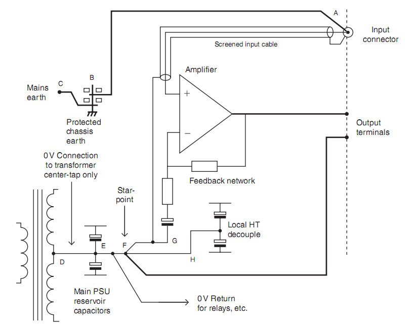
Should I connect Schaffner filter PE to input connector like in this picture?
Or maybe some other way? I have some stuff at home, PE cable is often connected with "the man in the middle", there is a 10-100R in series with PE cable and device ground (sometimes with capacitor in parallel to resistor to reject RF noise).
I'll stay with RC snubber across power line, my trafo vendor will send me values of Effective Interwinding Capacitance and Leakage Inductance so I'll probably be able to calculate exact values.
But now there is some other thing.
According to this picture (from Douglas Self book):
Should I connect Schaffner filter PE to input connector like in this picture?
Or maybe some other way? I have some stuff at home, PE cable is often connected with "the man in the middle", there is a 10-100R in series with PE cable and device ground (sometimes with capacitor in parallel to resistor to reject RF noise).
The PE (Protective Earth) is the third wire inside the mains cable that enters your equipment.
You permanently and mechanically fix that PE direct to the Chassis using a dedicated bolt that guarantees electrical connection.
Nothing else gets connected there.
If you choose to use an IEC socket with integrated filter, then that goes into the Chassis and it too is bolted in with good electrical connection. The third wire appears as a lug on the back of the socket. This gets a permanent wire connection to the Chassis using a dedicated bolt.
The PE wire is shown as "C" in D.Self's diagram. NOTE ! there is no resistor in that connection. NEVER fit anything into the permanent wire connection for the PE to Safety Earth. !!!
"B" is not good practice. Instead B should be moved to beside "A" where it gets bolted to the chassis.
However there is a flaw in this arrangement.
The "A" connection may in exceptional failure circumstances have to pass Fault Current approaching 1kA, until the mains fuse ruptures. Will the wiring leading to "A" be able to survive longer than it takes for the fuse to rupture and for the arc to extinguish?
I believe it is less risky to connect point "D, or E" to the Chassis as these are generally fairly thick/heavy wiring and much more likely to survive in the event of catastrophic failure in the mains wiring/connections.
Last edited:
I think you might mean, across the transformer secondary.I'll stay with RC snubber across power line ...
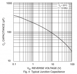
I strongly recommend that when calculating your snubber values, you employ a conservative OVERestimate of the capacitance of each of your diodes at zero bias. For example (the datasheet of the Schottky SB5100) shows a capacitance versus voltage plot in Figure 4. I suggest that you assume this diode's capacitance is 500 pF at Vf=zero.
Since your transformer secondary drives a bridge rectifier composed of four individual diodes, you will have to decide how much capacitance this entire assembly places across the secondary, at the instant of diode cutoff. Is it (0.5 * SingleDiodeCapacitance)? Is it (1.0 * SingleDiodeCap)? (2.0 * SingleDiodeCap)? Since the zero bias junction capacitance of an LTSPICE diode is known (it's SPICE parameter "Cjo" in the presupplied model), perhaps you can run some simulations to help you make this decision.
_
Attachments
Experimental reverse recovery waveforms indicate that diode junction reverse voltage starts to be sustained at the inflection of the reverse current flowing through the pn or sbd junction. Given that the inflection point is where the PT secondary winding experiences the affect of the diode switching dI/dt (ie. the toll of the bell), then the reverse voltage of two diodes is starting to increase above zero, and the other two diodes have voltages starting to fall from Vdc. The effective shunt capacitance of the bridge would vary a bit during the time of highest dI/dt, but I doubt the actual experimental snubber 'optimum' values would be very sensitive. Mark, have you seen any in-situ experimental waveforms with a given snubber that purposefully vary sbd capacitance (eg. by comparing waveforms using sbd with different current rating)?
Last edited:
- Status
- Not open for further replies.
- Home
- Amplifiers
- Power Supplies
- Proper RC Snubbering