Do not think of earth as a current sink, it is there for the PE connection only. !st rule of EMC.
Yes. It is not a sponge! and not part of a circuit? 🙂
@ AndrewT
Thanks, it helps regards clarity. My next question then would be. what happens to the interference noise that the chassis is screening the equipment from? Is it going to Earth?
"Rule 1. In Morrison [1] (page 39) states, “An electrostatic shield enclosure, to be effective, should be connected to the zero-signal reference potential of any circuitry contained within the shield.”" Quoted from the opening of http://www.diyaudio.com/forums/diya...udio-component-grounding-interconnection.html
The enclosure is capacitively coupled to "EARTH", the big ball we all stand/sit on.
The RF interfence passes via the lowest impedance to EARTH.
The internals may have multiple low impedance couplings to the enclosure via all the common mode RF attenuators (those caps from cables to chassis).
Does the low impedance enclosure to audio connection need to be effective down to DC?
Is RF coupling sufficient for the enclosure to be effective?
Yes, I was thinking just that. The capacitive coupling is enough. I've never been entirely comfortable with the direct 0V coupling to chassis but it has worked for me in practice. I shall experiment further, thanks.
Bonsai shows his recommended wiring of a two channel amplifier. He has not shown a DC zero ohms connection between audio and enclosure.Yes. It is not a sponge! and not part of a circuit? 🙂
I have been tinkering with a Sony CDP-591, it is class II, so no PE.
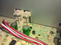
The 4 RCA barrels are made from a single piece of metal and bolted directly to the chassis. The circuit 0V/output ground has a very short connection from the edge of the board to the RCA's. What they have done is place small 100nF capacitors throughout the circuit connecting 0V/GND to the chassis.
The 4 RCA barrels are made from a single piece of metal and bolted directly to the chassis. The circuit 0V/output ground has a very short connection from the edge of the board to the RCA's. What they have done is place small 100nF capacitors throughout the circuit connecting 0V/GND to the chassis.
Then their ClassII (double insulated) construction is relying on the double insulation between all mains connected components never failing by sending Mains voltage to any isolated component/chassis.
That gives a clue to how onerous the Design, Manufacture, Test, and Guarantee is for a ClassII product. And how much more difficult that is to achieve in a metal chassis that is exposed to touch.
That gives a clue to how onerous the Design, Manufacture, Test, and Guarantee is for a ClassII product. And how much more difficult that is to achieve in a metal chassis that is exposed to touch.
Doesn't look too difficult to me. The transformer sits on the PCB and the mains fuse is hidden in the transformer. The mains cable is connected to the PCB with no switch.
Where DIY goes wrong is the long internal wiring. Connect the output to the chassis and design a short path to the power GND.
Where DIY goes wrong is the long internal wiring. Connect the output to the chassis and design a short path to the power GND.
1] AC power Protective Earth/Safety Ground should be permanently attached to the chassis near the AC power inlet.
2] All audio signal interconnect shields should be attached to the chassis at the connector.
3] Main Audio Ground (Audio Circuit Common) should be attached to the chassis near the input signal connectors.
******************
XLR balanced interconnects have no ground pin, pin#1 is the shield.
2] All audio signal interconnect shields should be attached to the chassis at the connector.
3] Main Audio Ground (Audio Circuit Common) should be attached to the chassis near the input signal connectors.
******************
XLR balanced interconnects have no ground pin, pin#1 is the shield.
I have been tinkering with a Sony CDP-591, it is class II, so no PE.
The 4 RCA barrels are made from a single piece of metal and bolted directly to the chassis. The circuit 0V/output ground has a very short connection from the edge of the board to the RCA's. What they have done is place small 100nF capacitors throughout the circuit connecting 0V/GND to the chassis.
Under those circumstances the Sony's chassis would only be coupled to Earth through the interconnects if the receiving equipment was DC coupled to Earth at signal return. Would it be better to directly couple the Sony's chassis to Earth if the signal returns were AC coupled to the chassis at the receiver?
I've just checked my Marantz CD6004, I have DC continuity between RCA ground and chassis
Last edited:
I don't know! Isn't just to do with RF screening?
Besides the safety element of course
Besides the safety element of course
Last edited:
Back to post 56. Rule 1 does not require an Earth connection, only that the shield must be connected to 0V/GND of the circuit. The shielding and 0V can be floating relative to planet Earth.
This I understand. What I'm having a problem with now is the following
When the chassis is used as shield for RF it needs to be connected to the Earth?
The enclosure is capacitively coupled to "EARTH", the big ball we all stand/sit on.
The RF interfence passes via the lowest impedance to EARTH.
The internals may have multiple low impedance couplings to the enclosure via all the common mode RF attenuators (those caps from cables to chassis).
Does the low impedance enclosure to audio connection need to be effective down to DC?
Is RF coupling sufficient for the enclosure to be effective?
When the chassis is used as shield for RF it needs to be connected to the Earth?
The cable that links the Protective Earth back to the mains distribution board (Neutral) has too high an impedance to be considered as part of an RF interference solution.
The "Earth" I referred to in post57 is stated as "the big ball we all stand/sit on."
My statement stand, many think of earth as the ultimate sink, hense these grounding boxes. Explain how we cater for RF interference on aircraft as I am doing now!!!
No earth is there for the PE connection that is really all it is for it is a safety feature, double insulated designs have no earth connection. As tsated in my last post aircraft have NO connection to earth, managed to get 18GHz RF immunity on some stuff for a trainer jet, vehicles have no earth connection in fact they are well isolated, get RF immunity for all the stuff we do to go in there, despite GPS and mobile phones everywhere.
Some reading matter...
One of my favorites...
http://sites.ieee.org/ctx-emcs/files/2010/09/Archambeault-Ground-Myth.pdf
some good links at the end of the article...
Planet Analog - Bruce Archambeault - The Ground Myth
One of my favorites...
http://sites.ieee.org/ctx-emcs/files/2010/09/Archambeault-Ground-Myth.pdf
some good links at the end of the article...
Planet Analog - Bruce Archambeault - The Ground Myth
As above, the Planet Earth has little to do with RF Interference.
Jim Brown the go-to EMI/RFI expert has done field experiments using portable power near a powerful radio transmitter. In some tests, a connection to Earth increased the interference.
Note that at some frequencies radio antennas do involve Earth.
Jim Brown the go-to EMI/RFI expert has done field experiments using portable power near a powerful radio transmitter. In some tests, a connection to Earth increased the interference.
Note that at some frequencies radio antennas do involve Earth.
This is a very clear article. Grounding and Shielding Audio Devices.
It also states that RF immunity can be increased by a low impedance connection to planet Earth. I get the impression though that this is easier said than done
It also states that RF immunity can be increased by a low impedance connection to planet Earth. I get the impression though that this is easier said than done
I cant find that reference... Do you mean this:
Conceptually, it is easiest to think of shields as an extension of the interconnected units' boxes (see Figure 1). Usually, metallic boxes are used to surround audio electronics. This metal "shell" functions as a shield, keeping electromagnetic fields in and out of the enclosure. For safety reasons, the enclosures in professional installations are required by law to connect to the system's earth ground (which in many systems is not the planet Earth -- an airplane is a good example).
- Status
- Not open for further replies.
- Home
- Amplifiers
- Power Supplies
- Proper grounding scheme