I guess they're on ferrite cores, no? Maybe even toroids? As such, they're pretty useless for 100/120 Hz filtration. And please have a look at their tiny inductancesI also picked up few different massive chokes that came out of an old solar inverter. Inductance ranges from mid 500s to low 900s of mH, but the DC resistance on them are tiny -- all sub 0.1 Ohms. I'd need to get a set of 4-wire probes for the multimeter to measure. Don't know if those would be useful for filtering in the power supply or not.
 ...
...Best regards!
Nope, not small ferrite core toroids, but large devices comparable in size/weight to the power/choke/output transformer I see in 100W vacuum tube amps. I'll post some pictures.
The tube amps you have are too heavy and loud. Throwing transformers choke and heat sinks together will be of lower weight? And how many watts do you want? For an apartment I would think in the single digits would do but you may have other ideas. Also we will not go running if we see some woodworking done, some of us have done it ourselves, from crates to enclosures that would not look out of place in a living room. I threw together a 25L6 amp using a 120V:6V adapter as output transformer and a 24V transformer for the heater, I can not remember the B+ supply I used but it was in the sub 100V range. It was only a proof of concept thing. It probably only put out a fraction of a watt but loud enough for a living room.
So not against using junk laying around to make an amp. But still confused at what it is you really want in terms of performance, outcome.
Edit:
So not against using junk laying around to make an amp. But still confused at what it is you really want in terms of performance, outcome.
Edit:
Somehow missed this post.Honestly, I think 20 Watts is the upper bound I'm willing to put across the speaker, given its rating of 40W. That's the common practice I've seen for amp power vs speaker power ratings: having the speakers rated for 2x or more the clean output power of the output stage. That makes sense, given that as the output stage is driven into clipping, power delivered into the load starts increasing rapidly, approaching 2x of the clean power as the clipped waveform approaches a square wave. I also don't want to exceed the voltage rating of the transformer so to avoid shorting it out with inductive flyback voltages if the output stage is ever driving into clipping, so 16Vrms is the upper bound. 16Vrms would give me 32W into an 8 Ohm load, but that's getting uncomfortably close to the speaker's 40W rating. So yeah, let's call 20W the upper bound of the target output power.
The tube amps you have are too heavy and loud. Throwing transformers choke and heat sinks together will be of lower weight?
Derp.
I was re-reading the explanations of chokes given on Aiken Amplification[1] in closer detail, and realize you're quite right about the weight part. The choke on a tube amp is commonly small, because it is often downstream of the +B supply fed to the output plates, and provides additional filtering to the screens and preamp. It isn't handling the full load current of the amplifier, and can thus get away with being as (relatively) small as it is. Were it upstream of the plates, it would be required to handle the full load current of the amplifier and would thus be much bigger and heavier. I'm willing to argue that the power transformer and output transformer of a solid state amp would be lighter at a given power level, because the solid state power transformer does not also have to drive screens and heaters. Transistors don't have a separate screen supply, and I would have to be able to deliver the full load current through the choke.
So, touché, sir. Thank you for binging me back to earth. I am forced to remember that such purely passive (and heavy!) designs are not necessary anymore. I can probably build a much quieter, stiffer, and lighter, power supply using some of the transistors to hand.
I'll toss the chokes back in the bin.
I got the casing off the doorbell transformer. The laminations are not welded, so rewinding it to a ratio more appropriate for an output transformer is in the cards.
1. https://www.aikenamps.com/index.php/chokes-explained
I have a thing for light weight amps now, been thinking about it for a while. Many ways to skin a cat though..
Small light weight amps are good for many things. Many years ago I made a 3 watt tube amp that went inside an electric guitar. It had a 4 inch speaker and ran from a 7.2 volt nicad battery from an RC car. Today we have lithium ion and bluetooth wireless. If I make another tiny amp that's on the menu.The tube amps you have are too heavy and loud......I threw together a 25L6 amp......
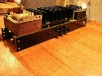
This little amp head chassis weighs less than 3.5 pounds. The cabinet weighs about 1.5 pounds. It makes 4 watts. The entire cost of material for this amp was under $50 when I built it. Some parts have gone up, especially the transformers. When used with my small speaker cabinet that contains a pair of 6 inch Parts Express speakers it is very loud in an 1800 square foot basement. maybe it's worth spending a few $ to get a transformer that's known to work.
The power transformer is a Triad N-68X which was $15 at build time, now almost $20. Any 1:1 120 volt isolation transformer rated for 50 VA or more will do. The OPT is a 70 volt line transformer from Parts Express, part number 300-040. It was $4 at build time, now $6. All of the tubes are still on the $1 list at VaccumTubes.net. I imagine that suitable mosfets would work as well, but I have not tried it yet. I did try a higher power version that used a voltage doubler circuit to get about 330 volts of B+ instead of 170. This netted over 10 watts of output but requires a bigger power transformer of at least 75 VA. This will boost the cost and weight a little. The little 300-040 transformer is good for about 10 watts in guitar amp use. Beyond that it gets lossy and shows signs of saturation especially if you plug a bass guitar into it. Don't go over 5 watts with a bass guitar.
The schematic is included and the original design as well as this redesigned version details are scattered throughout the Hundred Buck Amp Challenge thread which is a sticky thread in this forum.
Attachments
Kay Pirinha was wanting transistor counts. Here they are for the FETs
2N4856: Dozens
2N4858: Dozens
2N5114: Dozens
2N5115: Dozens
2N5462: 7
BUZ11: 13
BUZ54A: 18
IRCZ24: 2
IRF250: 1
IRF130: 3
IRF123: 9
MFP6661: 17
MTH50N05: 2
MTP10N25: 5
MTP:25N05: 22
MTP25N10: 12
MTP30P06: 3
Taking a look at datasheets, I think the JFETs (2N4856/8, 2N5114/5, 2N5462) and the MFP6661 will do fine for the the preamp. The MFP6661, with its 90V Vds max looks potentially promising for a trioderizer type circuit. I do think the high voltage (and thus input clipping threshold vs total available output voltage swing) was an important part of classic "tube sound"
The power amp section I'm having trouble with, however. These power MOSFets are intended for switching and handling 10s of amps of current -- they have much lower output impedances than the pentodes I'm used to. So much so that I can't draw a load line on these graphs -- any impedance at any step-down ratio between high volts on the output devices and low volts at the speaker would result in less current than the On Threshold gate voltage would produce across the device. Or the load line, once it passed over Vgs_On, would ride through the lower left corner of the graph where all the output curves are bunched together as they rise out of origin (0 drain current, 0 volts Drain to Source). I wonder if I were to get a curve tracer, if I could use it to zoom in on this section, to see if a load line were of any use here.
It seems that should I attempt to use these MOSFETs in common-source-push-pull-into-a-transformer like I see in tube output sections, instead of as source followers for boosting output current (as I've typically seen in diagrams), I would need a step-UP transformer to match the sub-Ohm output impedance to the 8 Ohm nominal impedance of the speaker. Setting aside any considerations of utterly damping the speaker so it produces no coloration at all (as opposed to the typical tube power amp wherein pentodes lose an argument with a speaker via a transformer), I'm not sure how the heck I'd build a power supply that could deliver the double digit current at single digit voltage needed to drive these power MOSFETs, given the power transformers I have to hand.
This is why most schematics I've seen have had something earlier in the output stage providing voltage gain, and then a complementary pair of BJTs or MOSFETs running as emitter/source followers driving the speaker, isn't it?
This is already hard as is. And yet I want to bring the misbehavior of a transformer into play when the characteristic impedances of both the output devices and the speaker say, "No". Y'all are officially allowed to call me silly while I attempt to figure this out.
In most SS amps with an output trafo, they just don’t use extreme turn ratios. It’s used to match a couple of ohms to 8 ohms, or somewhere around 8 ohms to a 70 or 100 volt line. You probably don’t want to drive a distributed speaker system so you can discount the latter. So why would you want to drive say, 2 ohms? In the early days of transistors, getting GOOD high voltage power transistors was next to impossible. On a 24-28 volt single power supply, one could safely obtain 100 watts with one pair of high current transistors, like the 2N5886’s in your stash. With a brute force +/-50 volt supply you would be playing with fire, running beyond max voltage rating (usually safe actually, if tested beforehand). The real issue is the severe power handling fall-off at elevated voltage which WILL blow them. Into an optimized impedance (in the 2 ohm range - again, with the right voltage) they’ll do it all day.
Too bad you only have one of those IRF250’s. A pair of those would make a VERY nice conventional output stage.
Too bad you only have one of those IRF250’s. A pair of those would make a VERY nice conventional output stage.
The correct type number for the little mosfet is MPF6661.
The usual schematics for mass produced solid state guitar and HiFi amps are driven by cost. Why use an output transformer if you don't have to. McIntosh did make some solid state power amps that used output transformers, but that was not the norm.
A typical mosfet can have a very low impedance. This is desirable. It can also be operated as a high impedance device if its ratings support such operation. There are mosfets capable of operation at voltages beyond 1000 volts. Some are capable of passing huge currents as well, and some are not. These devices are driven by the switching power supply market and usually not optimized for audio use, or any operation in the linear region for that matter. Some will even blow up if continuously operated in the linear region. Avoid linear operation with any mosfet where there is no curve for DC in the SOA graph, no SOA graph at all, or all of the suggested uses involve switch mode operation. Some switch mode devices mention "audio amplifier" but they are referring to a class D amp.
There are two kinds of mosfets, enhancement mode, the most common, and depletion mode. Your MPF6661 is an enhancement mode device. It will pass little or no current until a positive voltage is applied to its gate. A depletion mode mosfet biases up like a vacuum tube. It will draw lots of current with the gate lead unconnected. A negative voltage must be applied to the gate to reduce the current. There are high voltage depletion mode mosfets available that can often be dropped right into your favorite vacuum tube circuit. Most depletion mode fets can be safely used in the linear region.
I have literally stuck a pair of LND150 depletion mode mosfets right into the 12AX7 socket on a guitar amp and had them work. They are cheap at 50 to 70 cents each, but unfortunately out of stock currently at Mouser and Digikey. The DN2540 parts in the TO-92 case are in stock for about $1, but the TO-220 parts which are suitable for output duty are not stocked. Both are rated to eat 400 volts and work well in the linear region. The TO-220 version of the 350 volt DN2535 is stocked at under $2 each, and could work as an output device but there are better choices for an amp that could see severe overdrive into an inductive load. I have used the IXYS IXTP1R6N100D2 part successfully into an OPT. It can eat 1000 volts, pass up to 1.6 amps and dissipate 60 to 100 watts depending on how it is used. It is stocked and about $3.
All of the mosfets that you listed are about 20 years old, and only the MTP10N25 has a 250 volt rating. As you surmised you will need ample headroom for inductive effects and kickback when you crank it to 11, so you are limited to B+ voltages well below 100 volts. You will need about 12.6 volts RMS across that 8 ohm speaker to get 20 watts into it.
Your 120/208/240 : 24 volt transformers may make good choices for an OPT if their frequency response goes high enough. If you can find a sine wave generator and an oscilloscope, you can test them. Just put a sine wave into the full 240 volt primary and scope the secondary. Set the generator around 200 Hz or so and crank the amplitude up high enough that you get a measurable voltage on the secondary. Turn the frequency up until the secondary voltage starts dropping. You would like to see a small loss in voltage up to at least 5 KHz in a guitar amp. The transformer should have no problem passing 60 Hz and the lowest note on a guitar with standard tuning is about 82 Hz. Harmonics reach up to 5 KHz or more depending on the strings and pickups. Some "industrial control transformers" are quite lossy and do not have good high frequency response.
The 24 volt transformer would need 177 volts P-P on the 240 volt primary to put 20 watts into the speaker. This could be done with about 90 volts of B+ if the typical tube type output stage is used with B+ on the CT of the 240 volt input and the 24 volt output is used as the secondary. 90 volts is probably marginal with some 20 year old 250 volt mosfets. You could also use the typical CS solid state output stsge into the 120 volt winding, but you have no high voltage P-fets and they are rather rare at any price. The FQP9P25 goes to 250 volts, and has been declared "extinct" by the manufacturer but they are still in stock.
The older fets are also likely to have a rather high gate capacitance which can cause a loss of high frequencies and what a guitar player calls "tone suck."
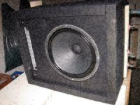
In the old days I built a transistor amp with 2xBUZ11 firing a self wound output xformer. It was fitted with an 15-inch speaker and delivered about 100W. This beast served several decades on all my live gigs.
Attachments
Last edited:

And now I am no longer in ultimate stage power. In case of bigger venues there is a line out to connect to the pa-system. I can say that the last decade was powered by TPA3116/TPA3118 exclusively. And TPA3251 for bass amplification.
Attachments
Derp.The correct type number for the little mosfet is MPF6661.
I don't think either of the 120/208/240V transformers I picked up are center tapped on the primary; the dc resistance is wrong. If it were a center tap, I would think I would see the same DC resistance, reflecting the same number of windings ,from Common to 120V as I see from 120V to 240, and twice that measuring from Common to 240V. Instead on the 120/208/240:19.2CT I measure:The 24 volt transformer would need 177 volts P-P on the 240 volt primary to put 20 watts into the speaker. This could be done with about 90 volts of B+ if the typical tube type output stage is used with B+ on the CT of the 240 volt input and the 24 volt output is used as the secondary.
- Common-120V: 23.6Ohm
- Common-240: 87.5Ohm
- 120-240:62.8. Ohm
Again on the 120/208/240:24 transformer, similar pattern
- Common-120: 14.1 Ohm
- Common-240: 58.3 Ohm
- 120-240: 44.0 Ohm
Not sure what's going on here, but that doesn't look like a center tap on the primary.
However, as mentioned with the doorbell transformer above, I've had the casings off and seen that the laminations are not welded together like they were with the first 120:24 transformer I found. So, there will be math involved and it will be a laborious task should I elect to do so, but rewinding is in the cards. Heck, I just might take some windings off the primary to lower the turns ratio and leave the secondary be.
I hadn't even thought of attempting to measure frequency response like this, thanks for the tip. I have access to a number of scopes, including a decent Rigol digital scope with a built-in sig gen. I poked it tonight and Sine is one of the functions the sig gen can do. I will take measurements of the transformers and report back what I find. Do you think re-winding the transformers, should I elect to do so, will appreciably change the frequency response, for better or worse, or will that be mainly dominated by the quality of the laminations? If 5kHz is the lower bound of acceptable high frequency losses, what's the upper bound? 10kHz? All the way to 20kHz? I did the math once and found that the 9th harmonic of E6 (so, high E, 24th fret) is some 19kHz and change. But I don't think you see much power in the 9th harmonic for much longer than the attack of the pick striking and releasing the string.If you can find a sine wave generator and an oscilloscope, you can test them. Just put a sine wave into the full 240 volt primary and scope the secondary. Set the generator around 200 Hz or so and crank the amplitude up high enough that you get a measurable voltage on the secondary. Turn the frequency up until the secondary voltage starts dropping. You would like to see a small loss in voltage up to at least 5 KHz in a guitar amp. The transformer should have no problem passing 60 Hz and the lowest note on a guitar with standard tuning is about 82 Hz. Harmonics reach up to 5 KHz or more depending on the strings and pickups. Some "industrial control transformers" are quite lossy and do not have good high frequency response
I got a Heathkit IT-1121 semiconductor curve tracer off eBay to measure what the output curves of whatever candidates end up selected, in hopes that knowing the actual turn-on/off voltages/currents of the devices lets me better design the circuit to behave how I want it to. The other thought was I can see if there's any room between the Ids and Vgs curves at the loads a 8Ohm speaker would present through a step down transformer. Not gonna lie, some of the graphs I've seen on these datasheets have been disheartening -- it looks like none of these transistors aren't interested in even turning on until they're passing 10 or more amps. 10 Amps across an 8 Ohm load is 80V and 800W. "Front of House engineers hate him! How do permanently destroy both your hearing and your loudspeakers with this One Weird Trick!" Also, depending on the winding ratio I stick with or rewind for, I'm not getting more than an amp or two from any of these power transformers.
Hah, I think all the MOSFETs in that list say they're designed for switching use. But At least a few of em have DC curves on their SOA graphs.Avoid linear operation with any mosfet where there is no curve for DC in the SOA graph, no SOA graph at all, or all of the suggested uses involve switch mode operation.
I'm noticing that when reading these datasheets. I see that the MTP10N25, for example, has an input capactiance of 1500pF. That's...not great. That's about 10x worse what would would typically deal with a typical 12AX7 gain stage. So, I'm going to need to pay attention to the input capactiances at play and size my resistors accordingly,The older fets are also likely to have a rather high gate capacitance which can cause a loss of high frequencies and what a guitar player calls "tone suck."
I'm honestly wondering if I should take another look at the BJTs -- I certainly have no shortage of options. IIRC, BJTs have pentode like output curves. They can't be pressed into Triode-like misbehavior (which might make that input capacitance worse?) but there might be some some options amongst the set that have musically-useful electrical misbehavior.v
In the old days I built a transistor amp with 2xBUZ11 firing a self wound output xformer. It was fitted with an 15-inch speaker and delivered about 100W.
Tell me more. What was your output topology? What were the turns ratio on your output transformer? What voltages were you running?
Tell me more. Are you thinking something like treating them similar to a pair of EL84s or 6V6s, run em at 100V or so push-pull on a center-tapped primary to get the output voltage swing needed for the target output current?Too bad you only have one of those IRF250’s. A pair of those would make a VERY nice conventional output stage.
Note that a power transformer with a really CT'ed primary needs thicker wire for the first, lower voltage section. Thicker wire of shorter length will necessarily result in much different DC resistances. The difference will not be that much with two isolated and equal primary halves that run in parallel for the lower and in series for the higher mains voltage.
Best regards!
Best regards!
There are two ways to make a multiple voltage transformer primary.I don't think either of the 120/208/240V transformers I picked up are center tapped on the primary; the dc resistance is wrong. If it were a center tap, I would think I would see the same DC resistance, reflecting the same number of windings ,from Common to 120V as I see from 120V to 240, and twice that measuring from Common to 240V. Instead on the 120/208/240:19.2CT I measure:
Compare the 19.2CT side, both 9.6 legs measure the same 0.3 Ohms to the center tap, and 0.6 to each other.
- Common-120V: 23.6Ohm
- Common-240: 87.5Ohm
- 120-240:62.8. Ohm
Again on the 120/208/240:24 transformer, similar pattern
Not sure what's going on here, but that doesn't look like a center tap on the primary.
- Common-120: 14.1 Ohm
- Common-240: 58.3 Ohm
- 120-240: 44.0 Ohm
The common method is two identical windings that are not interconnected that could be wired in series or parallel. One may have a tap for 208 or 100 volts. Here you will find two separate windings with similar, but not always identical DC resistances.
The other method is to wind one continuous primary with taps for every necessary input voltage. To put a given amount of power (VA or Watts) into that transformer the 100V (Japan) and 120V windings will need more current than the 240 winding, so a thicker wire must be used. Typically the zero volt end is the starting point and is closest to the core. once the 120 volt point is reached a thinner wire is used to complete the 120 to 208-240 volt part of the winding. On a larger transformer, or one with cost constraints the 208 to 240 volt part of the winding may also use a thinner wire than the 120 to 208 part. Since the transformer core aperture begins to fill up as the windings are added, the length of each turn becomes longer for each successive layer also making the DCR of the higher voltage windings higher than the lower voltage windings.
If the transformer was built using the second method, the DCR numbers you posted are not out of line. Put a known low AC voltage into the secondary and measure the primary voltages to determine if you have a true CT. Note that oddball transformers with some slightly mismatched primary halves are not desirable for HiFi applications but may be OK for a guitar amp.
I hadn't even thought of attempting to measure frequency response like this, thanks for the tip. I have access to a number of scopes, including a decent Rigol digital scope with a built-in sig gen. I poked it tonight and Sine is one of the functions the sig gen can do. I will take measurements of the transformers and report back what I find. Do you think re-winding the transformers, should I elect to do so, will appreciably change the frequency response, for better or worse, or will that be mainly dominated by the quality of the laminations? If 5kHz is the lower bound of acceptable high frequency losses, what's the upper bound? 10kHz? All the way to 20kHz? I did the math once and found that the 9th harmonic of E6 (so, high E, 24th fret) is some 19kHz and change. But I don't think you see much power in the 9th harmonic for much longer than the attack of the pick striking and releasing the string.
I have a bunch of OPT's that were custom made for ADA guitar amps by Schumaker in 1990. They are specified for "80 VA from 80 Hz to 5 KHz. That's where I came up with the 5 KHz number. In reality it's hard to make a transformer this bad, and these do go to about 20 KHz using the same laminations found in the battery chargers they made at the time. I don't think there is much of a reason for an upper bound in frequency response, as a higher upper rolloff frequency would improve stability if any feedback is applied in the amp. Most guitar speakers are dead (minimal response) by 5 KHz except for some small ones.
The guitar itself may have limited output above 5 KHz, usually limited by the pickup. Piezo's can go well beyond 20 KHz and can sound harsh if not rolled off. An amp driven into hard clipping can generate harmonics well beyond 5 KHz and often at a considerable level.
Note that welded laminations can kill the high frequency response and most microwave oven transformers that I have tested make really bad OPT's due to Eddy current losses.
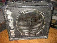
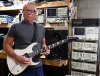
The little 4 watt 4 tube amp that I mentioned earlier is seen here on top of my budget "test speaker." The test speaker was made with a pair of somewhat inefficient $20 "Pro Audio" speaker drivers and a $15 "bullet tweeter" for testing high powered amps. I used cheap stuff so that I wouldn't cry much when I blew them up. Over 10 years later they still rock. The tweeter is mostly hidden by the guitar's neck, but part of the "bullet" can be seen just below the second fret. There is a switch on the back of the cabinet to turn the tweeter off. This is absolutely necessary when cranking even the 4 watt amp to 11 to prevent your ears from bleeding due to the HF content and I'm using a $5 OPT.
Attachments
It was a push-pull stage with 2xBZ11 that were configured as voltage controlled current sources. The output iron was a M84B laminated core with two intertwined primary windings, wired as a center tapped primary. Hand wound with 2mm dia magnetic wire. And that was all. The speaker was connected directly to the driving drains resulting in about 30W into 8 Ohms feeding with a 12V car battery and about 100W with the 20Vdc supply.Tell me more. What was your output topology? What were the turns ratio on your output transformer? What voltages were you running?
Tell me more. Are you thinking something like treating them similar to a pair of EL84s or 6V6s, run em at 100V or so push-pull on a center-tapped primary to get the output voltage swing needed for the target output current?
That’s the “autotransformer“ version of what I was thinking. With low enough B+ (30V) the DC voltage present at both speaker terminals isn’t a problem. But don’t get to crazy with it, or you’ll end up with an amp that you don’t want to play in church (If you found say 60VDC you might say some 4 letter words). An isolated winding will be “better” if you’re trying to get real watts. You only need say a 2:1 ratio making the winding relatively easy, and if the secondary is tapped you can match different speaker impedances without running the power transistors beyond the intended power levels. There is no real need to go up to “tube” voltages and step down - running lower volts more current can still provide output characteristics similar to a pair of push pull pentodes if that’s what you’re aiming for. Clipping will be “harder” but any solid state solution will do that.
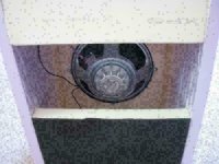
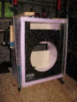
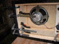
I've been wanting to do that for years. 🙂...I build an amp with ...a foamcore housing
Care to share any details on how you built the housing (cab)? For instance, what did you sheet the foam with (thin plywood?) How did you join the foamcore edges to make the cab? What sort of reinforcements did you add to carry the weight of the speaker and electronics? Et cetera. 🙂
-Gnobuddy
Usually wood baffle, foam core sides.
essentially Just a mold for the fiberglass fabric and resin
which makes it work.
Could be anything cardboard or foam
just a fiberglass enclosure.
Bass player forums use to be full of foam core builds.
Not much different than plastic commercial pa speaker.
Except Diy dont do injection molding.
So you have to build " a box" out of something
and cover it in fiberglass.
Far as the OP only so much to do with a 40 VA transformer.
10/ 15 watt amplifier not very demanding design.
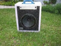
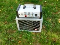
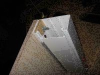
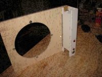
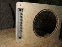
The front was regular baltic birch plywood that gave a good deal of stability. Glued it with regular white colle. There was no edge protection at that time - a big mistake! Besides the light box the amp is a light version as well, housed in a plastic cable tube.
Attachments
- Home
- Live Sound
- Instruments and Amps
- Project: Solid State Guitar Amplifier from Salvage & Obsolete Parts