

You mean propagation delay in the opto devices?
As long as the delay is the same for both devices and for rising and falling signals I don´t see any problem. It will just result in a total delay, but not affect the signal.
You just cannot add any NFB as it would be out of time.
As long as the delay is the same for both devices and for rising and falling signals I don´t see any problem. It will just result in a total delay, but not affect the signal.
You just cannot add any NFB as it would be out of time.

As long as the delay is the same for both devices and for rising and falling signals I don´t see any problem. It will just result in a total delay, but not affect the signal.
You just cannot add any NFB as it would be out of time.
You may of course apply feedback as long as the delay is distinctively lower than the clock period.
Feedback is mainly affected by the switching frequency. The unity gain point shouldn't be higher than half the switching frequency.
Edit:
Forgot to mention that this statement is only valid for carrier-based class-d amps. For self oscillating designs the unity-gain point is higher, since we deliberately want instability in order to cause oscillation. This increases the amount of NFB that can be applied for a given switching frequency.
Regards
Charles
Commentable Thoughts
Does self oscillating designs are more excellent and give better performance.
Does self oscillating designs are more excellent and give better performance.
I have never built a self-oscillating class-d amp (only carrier-based ones). The highly- praised Philips amps are self-oscillating so are the B&O ones (and also Lars' ZAP-pulse).
I only know the difference from simulations where the self-oscillating ones seem to be a little better as well (but simulations are simulations and real-world is real-world).
It is easier to take feedback from the output filter for self-oscillating topologies.
Apart from simplicity there are other advantages (one of them is good supply voltage suppression).
Some members here have built self-oscillating designs and they are convinced about their quality.
I by myself like the good carrier suppression one can achieve with carrier-based designs. Therefore I will build one in a feww weeks. It will also take feedback from the output filter (which is a little trickier than doing it with a self-oscillating design, but definitely not impossible).
Regards
Charles
Hi guys,
this is really interesting, if anyone gets a working prototype working, do shout it out.
I'd like to try my hand building one too.
Regards
this is really interesting, if anyone gets a working prototype working, do shout it out.
I'd like to try my hand building one too.
Regards
- Status
- Not open for further replies.
- Home
- Amplifiers
- Class D
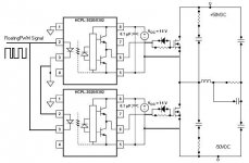
- Project : Practical Class-D PWM Subwoofer Amplifiers with optocoupled Gate Drivers