Hi folks,
For decades I’ve been dreaming of making digital audio system which would sounds indistinguishable from a good quality analogue one (based on tape or vinyl media).
But only recently it became feasible to build such a system for the reasonable amount of money, thanks to the new AD and DA converters (and other supporting chips) on the market.
Long story short – here is my first humble attempt, I called it Project IV.
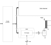
Generally, it’s a two-channel AD-DA converter (ADAC) built with high-end philosophy in mind and utilising industrial-grade ADC and DAC chips with good metrological parameters.
The ADAC board itself has balanced inputs, balanced and unbalanced outputs and supports 44.1, 48, 88.2, 96, 176.4, 192, 352.8 and 384kHz sampling rates.
Special steps were taken to reduce system jitter, including low phase noise Crystek 957 series oscillators and 13 low-noise linear LDO regulators on boar, mostly LT3042.
XMOS based DIYHK board is used as USB to I2S interface. Xilinx CPLD converts I2S signals to SPI interface, needed for multibit DAC, and forms sampling logic signals for SAR ADC chips (LTC2380-24).
While looking for information and app notes on LTC2380-24, I have come across very interesting project of Frex: https://www.diyaudio.com/community/threads/osva-open-source-versatile-analyzer.335005/
Highly recommend that thread for those thinking to use LTC2380-24 in their projects.
In my case ADC converter is always working at 1.536MHz for 48k band (or 1.412MHz for 44.1 band) sampling frequency. For 384k, 192k, 96k or 48k output LTC2380-24 chip does 4, 8, 16 or 32 averages respectively, thus improving S/N ratio. The same happens if 44.1k band is selected.
For DAC section I have selected 20-bit AD5791 (or 18-bit AD5781) chips. The reason is that since 2003 I love to use the following topology in my DACs:

It allows me to built a DAC with no feedback in any part of sound path, including reference and output buffer. Decades of intensive use has proven very good musical characteristics of this topology. And AD5781/91 chips have unbuffered R-2R matrix with no OP amp on the output.
Nevertheless, current PCB is allowing to use traditional schematic with high-quality OP amp buffers.
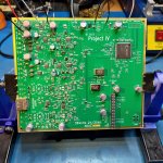
Overall view of the finished board is shown below:


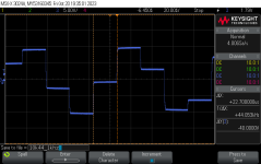
I have done some preliminary measurements of ADC section using low-distortion generator from (again!) Frex (https://www.diyaudio.com/community/...-10khz-oscillator-new-updated-version.287892/).
Found them quite satisfactory:


The next step now is to built tube buffers for ADC and DAC, so the work is in progress…
For decades I’ve been dreaming of making digital audio system which would sounds indistinguishable from a good quality analogue one (based on tape or vinyl media).
But only recently it became feasible to build such a system for the reasonable amount of money, thanks to the new AD and DA converters (and other supporting chips) on the market.
Long story short – here is my first humble attempt, I called it Project IV.
Generally, it’s a two-channel AD-DA converter (ADAC) built with high-end philosophy in mind and utilising industrial-grade ADC and DAC chips with good metrological parameters.
The ADAC board itself has balanced inputs, balanced and unbalanced outputs and supports 44.1, 48, 88.2, 96, 176.4, 192, 352.8 and 384kHz sampling rates.
Special steps were taken to reduce system jitter, including low phase noise Crystek 957 series oscillators and 13 low-noise linear LDO regulators on boar, mostly LT3042.
XMOS based DIYHK board is used as USB to I2S interface. Xilinx CPLD converts I2S signals to SPI interface, needed for multibit DAC, and forms sampling logic signals for SAR ADC chips (LTC2380-24).
While looking for information and app notes on LTC2380-24, I have come across very interesting project of Frex: https://www.diyaudio.com/community/threads/osva-open-source-versatile-analyzer.335005/
Highly recommend that thread for those thinking to use LTC2380-24 in their projects.
In my case ADC converter is always working at 1.536MHz for 48k band (or 1.412MHz for 44.1 band) sampling frequency. For 384k, 192k, 96k or 48k output LTC2380-24 chip does 4, 8, 16 or 32 averages respectively, thus improving S/N ratio. The same happens if 44.1k band is selected.
For DAC section I have selected 20-bit AD5791 (or 18-bit AD5781) chips. The reason is that since 2003 I love to use the following topology in my DACs:
It allows me to built a DAC with no feedback in any part of sound path, including reference and output buffer. Decades of intensive use has proven very good musical characteristics of this topology. And AD5781/91 chips have unbuffered R-2R matrix with no OP amp on the output.
Nevertheless, current PCB is allowing to use traditional schematic with high-quality OP amp buffers.
Overall view of the finished board is shown below:
I have done some preliminary measurements of ADC section using low-distortion generator from (again!) Frex (https://www.diyaudio.com/community/...-10khz-oscillator-new-updated-version.287892/).
Found them quite satisfactory:
The next step now is to built tube buffers for ADC and DAC, so the work is in progress…
Attachments


Again, great work! Did you build just the one or a few? I would love to try it and shoot it out against high end studio converters. I do think there is definitely a market for these things, BTW.
What's the reasoning behind using tube buffers? If low THD is the goal (I don't think we can hear any difference beyond 100 dB, but that's another issue) tubes probably won't help. May I ask which op amp you are using for the ADC part?
What's the reasoning behind using tube buffers? If low THD is the goal (I don't think we can hear any difference beyond 100 dB, but that's another issue) tubes probably won't help. May I ask which op amp you are using for the ADC part?
Thank you!Again, great work! Did you build just the one or a few?
It's a prototype for polishing the original design (I have never build an ADC before)
If it meet my expectations, I would build a few more, of course.I would love to try it and shoot it out against high end studio converters. I do think there is definitely a market for these things, BTW.
What's the reasoning behind using tube buffers? If low THD is the goal (I don't think we can hear any difference beyond 100 dB, but that's another issue) tubes probably won't help.
As I have mentioned in original post, my goal is to built a digital recorder which sound indistinguishable from the original analogue source of a good quality (tape or vinyl player). As an analog front-end, tubes usually help in this case. 🙂
And, in my opinion, you cannot compare directly THD performance of digital and analog systems as digital conversion distort sound in a different way than analog processing. All this sine-wave measurements are used to check that there are no major flaws in design.
For ADC driver I am using ADA4945-1 chips, they are a bit tricky (see my comment in original Frex thread), but provide a good performance.May I ask which op amp you are using for the ADC part?
As for DC offset, at this point it's not addressed, I am relying on manufacturer's spec for ADA4945-1 and LTC2380-24.
Without transformer-coupled tube buffer the ADC works from DC.
Without transformer-coupled tube buffer the ADC works from DC.
For ADC driver I am using ADA4945-1 chips, they are a bit tricky (see my comment in original Frex thread), but provide a good performance.
Ah, I see. I can't contribute anything regarding the digital side, but for op amps the PSU decoupling is critical. It is often best to use the highest-ESR electrolytic one can find (usually the physically smallest), since this provides the correct dampening of the power rails for stability. Isolating the PSU rails per op amp via some additional resistance can also help, as does adding resistance to small decoupling ceramics to counter trace inductance.
You probably know all of this.
I do agree that sinewave tests are mostly useful to confirm that things are OK in general. If you can do an acoustically transparent tube front end I am all for it (whatever works). But for balanced inputs you would then require a trafo or an additional electronic debalancing stage.
I do think that tried and tested op amps like the NE5534, with everything taken care of (especially decoupling) are good enough for audio. Most music we listen to has travelled through a lot of these things. But you won't get to the limits of the SAR chip this way. ;-)
But for balanced inputs you would then require a trafo or an additional electronic debalancing stage.
I already have balanced inputs, they provide 0dBFs at 3.712Vrms voltage swing (+11.4dBV sensitivity).
My tube buffer would provide single-end to balanced input conversion with balanced output trafo and some gain as well. 🙂
Short update.
Jumping from digital solid-state domain to analog tube one is not easy.
I have done my last tube project 12 years ago and got a bit rusty with tubes, thus slow progress so far.
At this moment I have selected 4 type of tubes and 3 topologies (one fully balanced) to try.
0 to -20dB 10 step bridge attenuator is also on the plate. Plus 3color LED level/clipping indicator similar to one Focusrite is using in their sound cards.
(UV meter would be a part of recording software)
As for the signal levels, I have decided to sacrifice a bit of S/N ratio and reduce balanced input level to around 1Vrms for 0dBFS. A passive, transformer-coupled stage can be used then. For single ended input +20dB voltage gain stage will provide100mVrms sensitivity.
That should cover most of user cases.
As DIYIHK board doesn't want to play 352.8/384kHz files correctly and chinese developers were of little help, now it's time to customize an original XMOS firmware to my project... Another learning curve!
After a few days of reading manuals, forums and tinkering generic software I have found a root case of my troubles with 384kHz playback. It turned out that USB-A port on my MS Surface 7 wasn't good enough! Switching to USB-C +HUB solution fixed the problem!
Now 10kHz@384kHz sampling rate looks very nice, especially, compared to 44.1kHz rate

Nevertheless, I am under opinion that it's incorrect device enumeration to blame. But at this point I am quite happy with an outcome as XMOS programming is a pure nightmare considering amount of information you have to absorb and digest.
Now, back to analog part...
P.S. Besides of quite complex programming and unintuitive tools, I was really impressed by XMOS platform - unlike normal microcontrollers, it has deterministic cores which can be programmed like simple logic state machine thus making CPLD chip redundant in design. Will definitely try this in the future.
Now 10kHz@384kHz sampling rate looks very nice, especially, compared to 44.1kHz rate
Nevertheless, I am under opinion that it's incorrect device enumeration to blame. But at this point I am quite happy with an outcome as XMOS programming is a pure nightmare considering amount of information you have to absorb and digest.
Now, back to analog part...
P.S. Besides of quite complex programming and unintuitive tools, I was really impressed by XMOS platform - unlike normal microcontrollers, it has deterministic cores which can be programmed like simple logic state machine thus making CPLD chip redundant in design. Will definitely try this in the future.
Attachments

Wonderful! I'm following the OSVA project here, but your design is exactly what I'm looking for!
I know this is too much to ask, but is it possible to have more synchronous I/O audio channels in the future?
If not, your project absolutely covers the maximum resolution of almost any analogue circuit. I look forward to project updates!
I know this is too much to ask, but is it possible to have more synchronous I/O audio channels in the future?
If not, your project absolutely covers the maximum resolution of almost any analogue circuit. I look forward to project updates!
Hi Mikae, at this moment I am working on analogue input/output buffers for the board but run to unexpected troubles with my primary job, so the progress is slow. As for multi-channel capability, I think it's quite possible (up to USB2.0 throughput limit) as XMOS board in use allows up to 8ch be used.
Hi, very interested in your project, any updates?
Is it open source? Want to follow your steps 🙂
Is it open source? Want to follow your steps 🙂
Hi folks, wow, time flies - it's already more than a year since my last update.
Sorry to keep you waiting but I was quite busy with a various stuff moving slowly this project to the end.
So, what has been done?
1. DAC tube buffer was developed using my favorite "Single Ended push-Pull" topology with 6GB8 tube in triode. I had to make 5 different output transformer designs until got happy with bandwidth and linearity.


2. To save development time for ADC buffer, a passive SE to BAL transformer stage was used based on UTC LH-519 transformers. All amplifications is done by ADC driver op amp.

3. For input and output level adjustment I have developed a versatile balanced binary step attenuator with constant input and output impedance plus SPLD-based encoder to binary code control circuit to avoid usage of noisy uCU. It's an exiting project by itself, and if anyone is interested, I can make it an open-source in a separate thread.

4. Due to noise pick-up had to move a power supply into different enclosure. I am using separate constant current sources for tubes filaments (to match tubes gain) and batteries for fixed bias.


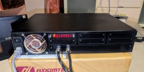
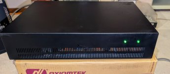
Complete project:

Now I am at measuring performance stage. My target is to reach or exceed studio reel-to-reel tape recorder performance.
So far did noise floor measurements, not disappointed!


Sorry to keep you waiting but I was quite busy with a various stuff moving slowly this project to the end.
So, what has been done?
1. DAC tube buffer was developed using my favorite "Single Ended push-Pull" topology with 6GB8 tube in triode. I had to make 5 different output transformer designs until got happy with bandwidth and linearity.
2. To save development time for ADC buffer, a passive SE to BAL transformer stage was used based on UTC LH-519 transformers. All amplifications is done by ADC driver op amp.
3. For input and output level adjustment I have developed a versatile balanced binary step attenuator with constant input and output impedance plus SPLD-based encoder to binary code control circuit to avoid usage of noisy uCU. It's an exiting project by itself, and if anyone is interested, I can make it an open-source in a separate thread.
4. Due to noise pick-up had to move a power supply into different enclosure. I am using separate constant current sources for tubes filaments (to match tubes gain) and batteries for fixed bias.
Complete project:
Now I am at measuring performance stage. My target is to reach or exceed studio reel-to-reel tape recorder performance.
So far did noise floor measurements, not disappointed!
Attachments


- Home
- Source & Line
- Digital Line Level
- Project IV: USB sound card with Hi-End twist