I'm thinking of building a stereo power amp based on Bob Cordell's error correcting MOSFET design.
For maximum laziness, I'm thinking of removing the power amp PCBs and power BJTs from a 1970's era receiver and replacing them with the new amp (probably built on proto strip board) and power MOSFETs. The idea is to reuse the existing heatsinks, power supply, chassis, and the entire tuner and preamp sections of the receiver. Optionally you could tune up the preamp by deleting tone controls, deleting coupling caps, and upgrading to a modern opamp. You could also use the existing speaker protection relay circuit.
Has anyone done this?
I guess the hurdles would be--
1- Identify a receiver or integrated with separate PCBs for each power amp that could be easily removed, and plenty of room for a replacement. Sanyo JCX-2600 or Onkyo TX-6500 mkII could maybe work? This is the Onkyo, look at all that space!

2- Identify a proto strip board that can fit in the target unit. Like one of these: https://www.futurlec.com/ProtoBoards.shtml
3- If the heatsink is set up for TO-3 output devices, identify suitable MOSFETs that come in TO-3 packages.
4- Can the amp design fit on the proto strip board selected?
For maximum laziness, I'm thinking of removing the power amp PCBs and power BJTs from a 1970's era receiver and replacing them with the new amp (probably built on proto strip board) and power MOSFETs. The idea is to reuse the existing heatsinks, power supply, chassis, and the entire tuner and preamp sections of the receiver. Optionally you could tune up the preamp by deleting tone controls, deleting coupling caps, and upgrading to a modern opamp. You could also use the existing speaker protection relay circuit.
Has anyone done this?
I guess the hurdles would be--
1- Identify a receiver or integrated with separate PCBs for each power amp that could be easily removed, and plenty of room for a replacement. Sanyo JCX-2600 or Onkyo TX-6500 mkII could maybe work? This is the Onkyo, look at all that space!
2- Identify a proto strip board that can fit in the target unit. Like one of these: https://www.futurlec.com/ProtoBoards.shtml
3- If the heatsink is set up for TO-3 output devices, identify suitable MOSFETs that come in TO-3 packages.
4- Can the amp design fit on the proto strip board selected?
If you are going to reuse the tuner and preamp, all those littel blue and black electrolytic capacitors need to go. I found the Sony Walkman FM radio I bought in 2006 had poor sensitiviey and selectivity, compared to a 1985 GE radio I had bought, and compared to my father's 1970? Reader's Digest radio. I had broken the GE radio by dropping it, and the RD radio had poor sensitivity and selectivity in 2010. So in 2010 I replaced all the electrolytic capacitors in the RD radio. No tuning tools, no alignment was undertaken. It just started working and sounding great. Needs a volume pot, purchased but not installled yet. Now my stalwart 1987 GE clock radio that took me through all those years when I couldn't buy tubes for my Dynakit hifi equipment, has started fuzzing out in cold weather (like yesterday). It is now due for all new electrolytic capacitors.
I find MOSFET's that are $4 in TO263, are $10 in TO3. So you may want to think about the heat sink some more. Drilling a few holes yourself should not be out of the question, if you have a vise, a hand motor, a set of number drills, and a dirty shop area. Use the mica washer for a pattern, and a sharpie to mark.
The Sony receiver I picked up for $7 at Salvation Army had preamp outputs, so you may want to compare your home build amp against the probuild one in the receiver, if you can't make it fit. Will take 2 more $4 capacitors to completely upgrade the power supply in the receiver.
I fit amp chassis in old metal recipe and letter files, cutting a hole for the heatsink and fan with drills, and a carbide Stanley hacksaw blade. Once you get to the straight cuts a regular 32 tooth hacksaw blade is faster. Salvation Army gets $2.50 for a recipe file and $4 for a metal letter file. Fans MOS surge surpressors etc come from dead PCAT power supplies, which blow up once a year like clockwork.
I make perfboard out of NEMA-CE laminate, and hold the junctions up off the metal with 1" long #6 screws and standoffs I cut out of 1/4" nylon air tube. For DIP packages, I use DIP project boards from mcmelectronics.com in OH, $2 each. The solder tends to bridge the pins on DIP packages without spreading the connections more than 0.1" apart.
Whether you can make the new board fit in the old case is up to you. Drawing it out is a good layout technique, IMHO.
Good luck.
Last edited:
Maximum laziness??
Maximum economy may be. You didn't mention anything about transformer voltage rating. That's the first thing you have to check. Cordell's have dual secondary transformer requirement. That's difficult to find in cheap amps. At least you have to add small transformer to lift the voltage for the driver/input stage. Maximum laziness?? I can tell you from experience that the chance you will complete this project is very small. Need huge effort here.
Maximum economy may be. You didn't mention anything about transformer voltage rating. That's the first thing you have to check. Cordell's have dual secondary transformer requirement. That's difficult to find in cheap amps. At least you have to add small transformer to lift the voltage for the driver/input stage. Maximum laziness?? I can tell you from experience that the chance you will complete this project is very small. Need huge effort here.
The Onkyo TX6500 II is already a decent 2 x 100W amplifier with dual 55V rails, uses well respected low noise components and after a refurb. with new caps, would sound great. The limiting factor will more likely be the parts you aim to keep, such as the old tuners, preamp, controls and and the wiring, which is a big factor in noise, crosstalk, hum etc. with all-in-one products.
If you like the style and functionality of this one, keep it as is. Transplanting the best SOTA amps in there will not only be inordinately difficult as Jay points out, but much of the benefit of improved amplifier designs will be lost in a receiver. That's an opinion of course, but I've done this myself and seen others try it to no benefit in big Akai, JVC etc. receivers. I'm just giving you my 2c to let you consider the practical aspects of putting the cart before the horse, electronically, so to speak.
The beauty of these old products is in their originality and those amps aren't really all that bad. See the service manual details here. If you have an amplifier that you want to completely gut, that's a different matter and you can make a much cleaner, low noise start where the quality of modern amplifier design and simpler, well separated power arrangements can be made to work together for better performance, as they should. 🙂
Has anyone done this?
I put a couple of power amps on old receiver chassis, reusing the power transformer. In one of them I installed another power transformer for a "dual monoblock" amplifier. I made my own front out of brushed aluminum.
However, Mr. Finch is spot on with his comments. I have never seen a receiver that didn't suffer from compromised layout; therefore much of the benefit of a superior power amp is wasted. Receivers use long audio cables and those awful plugs.
The smart money would restore the old Onkyo. They're pretty nice. 🙂
Cordell's have dual secondary transformer requirement. That's difficult to find in cheap amps. At least you have to add small transformer to lift the voltage for the driver/input stage.
Cordell's design shows +/-35V rails for the power MOSFETs and +/-50V rails for the frontend and drivers.
At risk of showing ignorance, why not use +/-50V for both? Does it blow up? Bob wrote:
"The boosted supplies for all circuits prior to the output stage enable the drive circuitry to provide adequate gate voltage to fully turn on the MOSFETs while maintaining margin against saturation."
I'm not sure what "margin against saturation" means. In a basic MOSFET amp, the power MOSFETs should stay in their saturation region basically all the time, no? What harm is there in applying a few extra volts at the drain? It doesn't seem like it should matter. Maybe I should play with this in spice.
Cordell's design shows +/-35V rails for the power MOSFETs and +/-50V rails for the frontend and drivers.
At risk of showing ignorance, why not use +/-50V for both? Does it blow up?
No, it does not blow up. But it significantly increases output power dissipated by the output devices, without increasing the out power to the load.
It means what is says. It allows the devices to be fully turned on, without saturating them.Bob wrote:
"The boosted supplies for all circuits prior to the output stage enable the drive circuitry to provide adequate gate voltage to fully turn on the MOSFETs whilemaintaining margin against saturation."
I'm not sure what "margin against saturation" means.
Most definitely not.In a basic MOSFET amp, the power MOSFETs should stay in their saturation region basically all the time, no?
"A few extra volts" is 30% more voltage in this example. This greatly increases power dissipation for the output devices.What harm is there in applying a few extra volts at the drain?
Most definitely not.
Does "saturation" mean more than one thing?
I built a spice model of Cordell's simple MOSFET amp. At idle, the power nMOS has Vgs = 2.3V, Vds=35V.
That's saturation, no? We would be somewhere way off the right-hand edge of the diagram:
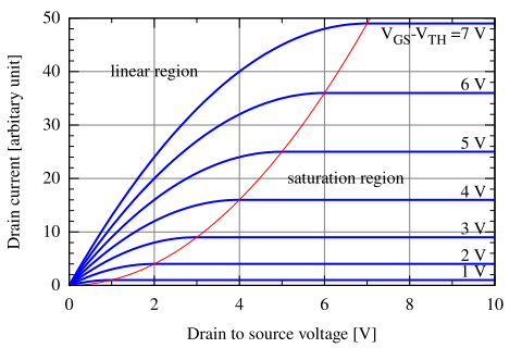
LTspice for the simple amp attached.
Attachments
The amp boards are attached to the heat sinks.
layout your cordell amplifier single channel boards matching the output transistor and mounting positions on the heat sinks.
you can also place connectors in the same places. not as important as the mounts. The middle board is likely the tuner replace caps if nescessary.
Replace both the large caps with equal or greater values of voltage and uF.
the 50v supply can come from a voltage doubler and regulator off the main output winding of the transformer. this may require another smaller custom board.
At risk of showing ignorance, why not use +/-50V for both? Does it blow up? Bob wrote:[/SIZE][/FONT]
"The boosted supplies for all circuits prior to the output stage enable the drive circuitry to provide adequate gate voltage to fully turn on the MOSFETs while maintaining margin against saturation."
I'm not sure what "margin against saturation" means. In a basic MOSFET amp, the power MOSFETs should stay in their saturation region basically all the time, no? What harm is there in applying a few extra volts at the drain? It doesn't seem like it should matter.
You are right about how it operates. The text you quoted was talking about increasing drive voltage to 50v so that sufficient Vgs can be achieved even if Vds is only 35v. Of course with Vds 50v you are well above cutoff which is fine from saturation pov.
But increasing Vds will compromise the design in usually many ways and you have to check it (I currently don't have computers). Like has been mentioned, heat is the obvious consequence and you may run out of heat sinking.
You are right about how it operates. The text you quoted was talking about increasing drive voltage to 50v so that sufficient Vgs can be achieved even if Vds is only 35v. Of course with Vds 50v you are well above cutoff which is fine from saturation pov.
Thank you.
I would like to ask the OP, what kind of linear amplifier would operate its output devices in saturation mode? Saturation of output devices = clipping. Saturation of output devices at idle =shorted output devices, for all practical purposes.
Even with BJT output devices, supplying the voltage gain/input stages a higher voltage than the output can increase linearity of the amplifier at high voltage output. It also helps avoid latch up. 😎
On that note, I wish you luck with your project.
- Status
- Not open for further replies.
- Home
- Amplifiers
- Solid State
- project idea. custom amp board in old receiver