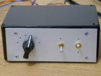
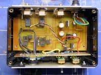
This little project is a continuation of the SEAS Exotic FR build.
https://www.diyaudio.com/community/threads/seas-exotic-f8-speaker-build.382000/
It might be useful for other DIYers. With adjustment of the component values it can be used to provide baffle step compensation or the HF step down to equalise units with a rising FR. This one is built with components for the latter purpose. Having used L,C and R networks in the speaker leads to adjust the frequency response I had arrived at several combinations that sounded good.
I thought it would be better if I could get rid of the boards with these components both for technical and aesthetic reasons. The simplest way to try this is just to put a few resistors and a capacitor between the source and the power amplifier as is well known. I started with Rod Elliott's circuit. This is a development of that.
By inspecting the step down of the LCR network in xsim I calculated the R C values to give similar FR cuts. To avoid a pot I used a rotary switch to create part of an attenuator with resistors giving the steps that I wanted. The cuts are 0dB, -2.5dB,-3.5dB,-4.6dB, -6dB and -7.5dB. Matched components give accurate channel matching. A buffer after the network improves the accuracy of the shaping. As I was going to the trouble to make this, I added a switch to select two values of capacitor, setting the corner freq at 1kHz or 1.8kHz. Another switch selects between two inputs. These were put into a small plastic box with a remote dc supply. In the one small box we have effectively two large inductors, capacitors and 5 resistor values per channel. The result is very convenient to use and the FR can be changed easily while listening.
I had most parts to hand (except some pcb board and a new rotary switch) – even the plastic project box. The box turned out to be more trouble because as I went along I had to cut it about and make front and back panels of spare alloy, all a bit rushed and bodged, so not elegant.


Thanks for your comments, I felt sure this must have been done many times, I think it's a better solution than the traditional approach with inductors in the leads.Nice!
I did something similar many years ago, integrated in a DIY pre-amp with an LME49740 op-amp. I had a linear taper pot varying from 0dB to -6dB at a fixed frequency for the intended speaker.
Last edited: