Hello
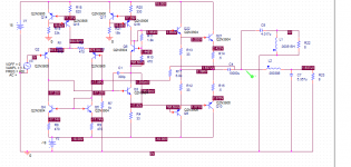
The Vbe multiplier to bias the output stage is not working correctly in my amp. When I disconnect the output stage from the rest of the amp, it works fine, dropping about 2.9V. However, when I hookup the output stage, the voltage across the Vbe multiplier jumps to about 11 or 12 Volts, which fries the resistors in the output stage. Maybe the base current drawn by the output stage is messing it up. I am at a loss because the PSPICE simulation of the circuit runs smoothly. Are PSPICE results generally not very close to reality? This is my first amp so I don't have much experience here. I have a picture of the circuit. The only difference is that I'm using BC337 for the small signal NPN and TIP31C and TIP42C for the output transistors. Anybody have any similar experiences that they could share with me?
Thanks
Attachments
Spice sim usually agrees pretty well for this kind of stuff, given good models...
a few questions...
1. are your really using 2N3904/06 for the output devices? They will last about 2 milliseconds in this application.
2. 2N3904/06 as drivers also aren't long for this earth...if things are working well, they would dissipate almost 350 mW...but not for long!
3. feedback to R17 is taken on the wrong side of C4...there's no DC feedback...so you see the input stage voltages look suspicious...
Perhaps I'm just mis-interpreting some of the connections, so please feel free to set me straight...
Spice sim usually agrees pretty well for this kind of stuff, given good models...
a few questions...
1. are your really using 2N3904/06 for the output devices? They will last about 2 milliseconds in this application.
2. 2N3904/06 as drivers also aren't long for this earth...if things are working well, they would dissipate almost 350 mW...but not for long!
3. feedback to R17 is taken on the wrong side of C4...there's no DC feedback...so you see the input stage voltages look suspicious...
Perhaps I'm just mis-interpreting some of the connections, so please feel free to set me straight...
I am using power BJTs for the output. So you're saying that the negative feedback should be on the left side of the coupling cap?
Use the TIP31C and TIP42C power transistors in your simulation.
.MODEL TIP31C NPN (IS=3.16P NF=880M NR=880M RE=391M RC=1 RB=10 VAF=40 VAR=20 ISE=140P ISC=140P ISS=0 NE=1.6 NC=1.6 NS=1 BF=379 BR=5 IKF=266M IKR=266M CJC=131P CJE=131P CJS=0 VJC=515M VJE=515M VJS=750M MJC=330M MJE=330M MJS=0 TF=2.65N TR=345N EG=1.11 KF=0 AF=1)
.MODEL TIP42C PNP (IS=5.65618e-10 BF=120.073 NF=1.24004 VAF=90.6071 IKF=1.46498 ISE=6.98929e-14 NE=4 BR=2.83268 NR=1.30331 VAR=27.1221 IKR=10 ISC=6.98934e-14 NC=3.78125 RB=4.71382 IRB=0.234602 RBM=0.12691 RE=0.000666374 RC=0.0927424 XTB=3.21145 XTI=1 EG=1.05 CJE=1.93221e-10 VJE=0.4 MJE=0.259369 TF=9.99163e-09 XTF=4.41941 VTF=6.53488 ITF=0.001 CJC=1.0962e-10 VJC=0.731968 MJC=0.23 XCJC=0.799902 FC=0.799995 CJS=0 VJS=0.75 MJS=0.5 TR=1e-07 PTF=0 KF=0 AF=1)
Tou will need something more beefy for pre-drivers as well.
Last edited:
I am using power BJTs for the output. So you're saying that the negative feedback should be on the left side of the coupling cap?
Definitely do as djoffe says regarding the feedback take off point.
Could the amp be oscillating ? Try slapping a 22pf cap across R17.
V1 and V2 are correct as evidenced by the voltages in the simulation. The symbol is of a of a "polarised battery", presumably 0.00 volts as default, and its told to be a -18 volt battery by the user. The symbol, remaining unchanged by this, is then "incorrect" according to normal convention.
Confusing... I agree.
Confusing... I agree.
So I took out the ouput cap completely as djoffe recommended. Now the Vbe multiplier is dropping a nice 3V but there is still a ~4.5 V drop across R14 for some reason which obviously results in way more current than it
can handle. I also checked the difference between the emitters of the pre-drivers and that was around 10V I don't understand how that's even possible given the difference at the bases of the pre-drivers is only 3V due to the Vbe multiplier. At this point I'm just thinking that either I'm hooking it up wrong or these components are fried from all this abuse and I should maybe replace all the transistors and resistors in the output stage. I'm assuming it's the latter because I have checked over my work several times...
can handle. I also checked the difference between the emitters of the pre-drivers and that was around 10V I don't understand how that's even possible given the difference at the bases of the pre-drivers is only 3V due to the Vbe multiplier. At this point I'm just thinking that either I'm hooking it up wrong or these components are fried from all this abuse and I should maybe replace all the transistors and resistors in the output stage. I'm assuming it's the latter because I have checked over my work several times...
First thing to do is apply a short across the vbe multiplier. That forces the voltage and output stage current to zero. The amp should work correctly in that state with just a small amount of distortion.
I would rebuild and recheck the amp doing that and only when its working correctly move on to adjusting and testing the vbe multiplier.
Did you try a cap as I suggested (although it won't help if parts are zapped of course)
I would rebuild and recheck the amp doing that and only when its working correctly move on to adjusting and testing the vbe multiplier.
Did you try a cap as I suggested (although it won't help if parts are zapped of course)
- Status
- This old topic is closed. If you want to reopen this topic, contact a moderator using the "Report Post" button.
- Home
- Amplifiers
- Solid State
- Problems with Vbe multiplier