An open amp solution driving a mosfet will work quite well with a minimum voltage overhead to the negative supply. An excellent circuit topology for a precision current source.
Looking at the circuit you simulated, I would be concerned. It looks as if you are making use of the op amp input bias current to generate the 10 mV bias. If so you will find that the actual circuit will behave quite unpredictably. In reality, not spice, input bias current varies considerably from device to device and generally has considerable temp dependence.
Looking at the circuit you simulated, I would be concerned. It looks as if you are making use of the op amp input bias current to generate the 10 mV bias. If so you will find that the actual circuit will behave quite unpredictably. In reality, not spice, input bias current varies considerably from device to device and generally has considerable temp dependence.
Your original question and problem is a great learning example of how simple things are not, and the dependence on spice as a way to fill in knowledge gaps. Not criticising you, but it highlights how quickly one can get into trouble. Everyone can improve their skills and success if they did some study of basic transistor device physics or models.
Good luck!
Good luck!
Looking at the circuit you simulated, I would be concerned. It looks as if you are making use of the op amp input bias current to generate the 10 mV bias. If so you will find that the actual circuit will behave quite unpredictably. In reality, not spice, input bias current varies considerably from device to device and generally has considerable temp dependence.
What would be better then?
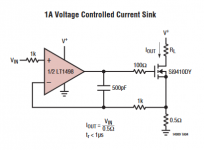
Those parts do do things. There can be a tendency to oscillate. They provide frequency compensation. As long as mosfet input capacitance is reasonably low, and the current monitoring resistor is not to small, they will likely not be needed for your design. Make sure that the op amp input common mode range includes its negative supply or is provided with a negative supply with respect to your ground.
What would be better then?
Attachments
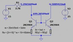
I'm having trouble following your examples...why is "re" capitalized and "Re" not?
Anyhow, that design doesn't work with REq1 and REq2 1Ω-100Ω. I only tried same values for both.
Anyhow, that design doesn't work with REq1 and REq2 1Ω-100Ω. I only tried same values for both.
Last edited by a moderator:
I had it working with the LT1498 on a breadboard, swapped it out for a LM358 and now it doesn't work anymore...I really hate breadboards.
This is still above my paygrade at the moment, you're going to have to dumb it down...why do I have to "Make sure that the op amp input common mode range includes its negative supply..."?
Make sure that the op amp input common mode range includes its negative supply or is provided with a negative supply with respect to your ground.
This is still above my paygrade at the moment, you're going to have to dumb it down...why do I have to "Make sure that the op amp input common mode range includes its negative supply..."?
- Home
- General Interest
- Everything Else
- Problems with simple current mirror