I set up the below circuit on my workbench, using the RL15a pentode driven by Mosfets. It is inspired by the work by Michael Koster https://www.diyaudio.com/forums/tub...artial-feedback-se-amplifier.html#post2709572
The RL15a is biased at around 18W, but I am getting only a clean 2W out of this circuit. I played around with operating points, but I always get stuck at very similar looking sine waves on my scope – so maybe it is something different than the circuit.
https://frank.pocnet.net/sheets/183/r/RL15A.pdf
The Pictures.
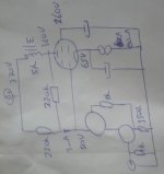
1 - schematic, a cascode using the 2SK715 and DN2540.
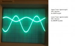
2 – at low level, sines at grid and plate look nice
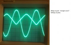
3 – at about 2,5W, sines at plate looks good, measured DHT is about 0.8%. But signal at grid looks a lot like a triangle wave. Why?
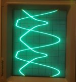
4 – increasing the level further. Both plate and grid show a dip. Plate and grid are connected with the resistor and the current through that resistor is more or less linear, so a dip in either will be directly reflected in the other? But which dip came first? Is the OPT not up to the task?
Many thanks for looking!
Erik
The RL15a is biased at around 18W, but I am getting only a clean 2W out of this circuit. I played around with operating points, but I always get stuck at very similar looking sine waves on my scope – so maybe it is something different than the circuit.
https://frank.pocnet.net/sheets/183/r/RL15A.pdf
The Pictures.
1 - schematic, a cascode using the 2SK715 and DN2540.
2 – at low level, sines at grid and plate look nice
3 – at about 2,5W, sines at plate looks good, measured DHT is about 0.8%. But signal at grid looks a lot like a triangle wave. Why?
4 – increasing the level further. Both plate and grid show a dip. Plate and grid are connected with the resistor and the current through that resistor is more or less linear, so a dip in either will be directly reflected in the other? But which dip came first? Is the OPT not up to the task?
Many thanks for looking!
Erik
Attachments
330v p-p signal looks alright , input is odd. that translates to around 6w into 8 ohms.
65v on anode may be a little high, 9w is probably about the most power to expect (1/2 idle power). 4th image shows clipping on the low side. I would try to get the anode voltage under 40. This is why output tubes are biased with a negative supply.
-5v grid bias would leave 10v for current bias and bypass capacitor.
I would try a 2.2m grid bias resistor and .1uf 100v mylar cap from 50v position to grid.
Last edited:
You'r driving the tube in positieve grid region to get enough current for the anode voltage swing.
To little heater current, load is much less then the 5k or the tube is used.
Mona
To little heater current, load is much less then the 5k or the tube is used.
Mona
Last edited:
How would feedback work if you had the same signal on the grid like on the anode?
The signal on the grid includes compensation of non-linearities of anode signal, that is more distorted the more distortions it compensates. It is absolutely normal.
The signal on the grid includes compensation of non-linearities of anode signal, that is more distorted the more distortions it compensates. It is absolutely normal.
Many thanks for the replies!
Wavebourn. You are talking about the 3rd picture, with the "triangle wave" at the grid? Yes, off course you are right that correction has to be applied somewhere: the output should look nice and some "intermediate" signal gets nasty looking to accomplish that.
Biggest question is why the output sine is not nice at the 4th picture anymore. One of the first things I am going to test is indeed a Source follower between the drain of the fet and the tubes grid, to isolate the possible low input impedance of this grid. Will also try a different tube and different OPT.
i cant make a lot of sense of stocktraders reaction. The grid (and drain of mosfet) is at 50V and the cathode at 65V, so the tube is biased "normally", with cathode 15V higher than the grid. I choose 50V at the grid so that the mosfet can swing 30Vpp with some marging without the drain getting below 25VDS (capacities at lower than 25VDS do not look very nice). Testing an AC coupled one may indeed make sense.
thanks again,
Erik
Today I had time to play with the circuit again, but with a GU50 instead. Performance was even worse - until I realized I had forgotten about one of the grids, the one that is barely talken about, the 3rd Grid! I had left it disconnected/floating. As soon as I connected it to the cathode, I got a substantial power output.
Went back to the RL15a and there the 3rd Grid was attached to Gnd. Changed that connection to the cathode, and now I am getting some 5W - 6W out of the circuit. Still to do the fine tuning, but it was the negative potential on G3 that was limiting the plate swing.
Thanks again for the support!
Erik
Went back to the RL15a and there the 3rd Grid was attached to Gnd. Changed that connection to the cathode, and now I am getting some 5W - 6W out of the circuit. Still to do the fine tuning, but it was the negative potential on G3 that was limiting the plate swing.
Thanks again for the support!
Erik
Try something like +10V on G3 in respect to cathode, you can add voltage to G2 then, getting a bit more output power.
www.wavebourn.com • View topic - GU-50
www.wavebourn.com • View topic - GU-50
- Status
- Not open for further replies.
- Home
- Amplifiers
- Tubes / Valves
- Problems with hybrid circuit / partial feedback.