Hey, I found this transformer on RS components website:
RS | Transformers | Transformers | Chassis Mounting Transformers | Open Laminated Clamp & Frame 230Vac Primary, 6VA to 50VA |10-5859
It says 2 x 6.3V output. I assume this means it is center tapped?
Please let me know if you see any problems using this transformer, as there are others available but I thought it would just be easier if I ordered everything from one place.
Thanks
There's nothing wrong with it but it is waaay oversized for your project. Unless you intend to tear it apart and recycle the transformers you should look for something like this, you can almost get both transformers you need for the price of the one above (you'd still need two of those).
If you can find even cheaper 5 VA or thereabouts ones (these usually come in PCB mount version only), you can easily use those. EM87 requires less than 2W for heater and less than 0.5W for B+ supply.
If you can find even cheaper 5 VA or thereabouts ones (these usually come in PCB mount version only), you can easily use those. EM87 requires less than 2W for heater and less than 0.5W for B+ supply.
I found this one below, it is basically the same as the one you found be just a 230V input instead of 2 x 115V. It is also a fraction cheaper.
RS | Transformers | Transformers | Chassis Mounting Transformers | Open Laminated Clamp & Frame 230Vac Primary, 6VA to 50VA |10-5842
I seem to be having a few problems with my transistor circuit and may move to an op-amp design.
If I do the op-amp design I may need higher voltages for the rails.
If I buy the below transformers
RS | Transformers | Transformers | Chassis Mounting Transformers | Open Laminated Clamp & Frame 230Vac Primary, 6VA to 50VA |10-5844
Then is it safe to connect the heaters in series to one of the 12V outputs?
E-series tubes were designed for parallel heater operation. This being said, I don't think there'd be any harm to tubes if you connected 2x EM87 heaters in series. If you were concerned about the startup (uneven warmup of heaters), you could use DC heater supply with simple CCS (LM317).
However it is my opinion that you're complicating things waaaay too much. You need 10V peak-to-peak on grid to drive the EM87 to full excursion. Those 6V secondary transformers (first link in your most recent message) will provide cca. 15V post rectifier, voltage doubler and filtering, which is more than enough to get even the cheapest LM358-type of opamp to generate 10V swing.
However it is my opinion that you're complicating things waaaay too much. You need 10V peak-to-peak on grid to drive the EM87 to full excursion. Those 6V secondary transformers (first link in your most recent message) will provide cca. 15V post rectifier, voltage doubler and filtering, which is more than enough to get even the cheapest LM358-type of opamp to generate 10V swing.
I may not need a voltage doubler, as when I was testing the tubes I found that a voltage around -6V or so would provide enough deflection so that the lines meet in the middle.
I don't really want them to overlap much or not at all.
I also found changing some of the resistor values changes these results.
Below is my updated schematic, it is a bit of a mess...
I have changed the transistor circuit to an op-amp one.
The simulation looks much more promising than the transistor one as well.
It is just a peak follower with an inverting amp.
From what I can tell I have connected the bridge rectifiers correctly for the + and - voltages for the opamps.
I was unsure if the center taps should be connected to each other.
Please let me know if you see any more problems.
Thanks
I don't really want them to overlap much or not at all.
I also found changing some of the resistor values changes these results.
Below is my updated schematic, it is a bit of a mess...
I have changed the transistor circuit to an op-amp one.
The simulation looks much more promising than the transistor one as well.
It is just a peak follower with an inverting amp.
An externally hosted image should be here but it was not working when we last tested it.
From what I can tell I have connected the bridge rectifiers correctly for the + and - voltages for the opamps.
I was unsure if the center taps should be connected to each other.
Please let me know if you see any more problems.
Thanks
The tube part looks fine, not the opamp supply part though (see below) ! You don't have to connect center taps together (as a matter of fact if two transformers aren't exactly the same connecting them could cause unwanted side effects).
If you're using Cadsoft Eagle to draw your schematic, download tubes.lbr library. It contains tube symbols, among them EM87. Use it, your schematic looks a bit confusing with those points scattered all around.
Regarding symmetrical opamp supply: it is messed up, you can't just connect two bridge rectifiers fed from the same source on top of one another !!! If you really need symmetrical supply (why ?) use two diodes (something along the lines of SB130 schottky should do fine), half wave rectifier for V+ and V-, and connect ground reference for the entire circuit to the center tap !
If it was me I'd change the circuit entirely and get rid of silly complications: schottky or germanium rectifier + smoothing capacitor on audio input, single-sided supply for low voltage parts, simple PNP amplification stage to provide grid bias.
I have made an attempt to design a PNP amp for the grid bias, unfortunately I haven't had much luck. The rectifier seems to do its job.
My PNP design is quite poor. I would appreciate it if you could possibly help me out on this or refer me do a decent guide.
I am unsure of what is needed from the rectifier, but below is a simulation showing the voltage across R2
I know the op-amp thing will work, but as you said I am over complicating things
Many thanks yet again
My PNP design is quite poor. I would appreciate it if you could possibly help me out on this or refer me do a decent guide.
I am unsure of what is needed from the rectifier, but below is a simulation showing the voltage across R2
An externally hosted image should be here but it was not working when we last tested it.
I know the op-amp thing will work, but as you said I am over complicating things
Many thanks yet again
There are many transistor guides avaliable online, pick any one and read it thoroughly. Alternatively, post the schematic of your existing underperforming version so people can fix it for you.
Well I have been experimenting in Ltspice and have had limited success.
I constructed the npn transistor amplifier from my original post, however results from the simulation and the actual circuit differ quite a bit.
Below is the PNP version I tried, this sort of works. For a maximum input of 1V p-p it generates -4.5V out, this is a bit low and I am struggling to get it higher.
It is also not very linear, generating -3.5V for 0.5V p-p and -2V for 0.25V p-p.
The supply I took as the rectified voltage of -6V minus 1V safety for volt drop in the rectifier, however if I use schottky diodes then this will be closer to -8.5V.
I will carry on trying some new things and post the results if I have any luck
I constructed the npn transistor amplifier from my original post, however results from the simulation and the actual circuit differ quite a bit.
Below is the PNP version I tried, this sort of works. For a maximum input of 1V p-p it generates -4.5V out, this is a bit low and I am struggling to get it higher.
It is also not very linear, generating -3.5V for 0.5V p-p and -2V for 0.25V p-p.
The supply I took as the rectified voltage of -6V minus 1V safety for volt drop in the rectifier, however if I use schottky diodes then this will be closer to -8.5V.
An externally hosted image should be here but it was not working when we last tested it.
I will carry on trying some new things and post the results if I have any luck
Look, you won't get 10V of swing with 7.5V collector supply, is that clear ? It is physically impossible. I told you how to get 15V or so out of that transformer without much hassle.
Your collector resistor is huuuuuuge. Try something more reasonable, say 10K collector load and few K || 10 uF in emitter. My LTspice says this gives 10V peak with 15V supply and clips heavily (for maximum possible brightness with only half-wave rectified signal).
Don't worry about linearity - most music you'll be listening to wouldn't move the indicator much at all so you'll have to drive your indicator (this transistor circuit) into clipping at some reasonably loud level, making it nonlinear by definition. In addition to that you're losing some voltage in rectification (should you decide you want indicator to light to full brightness, again resulting in nonlinearity. Ultimately, nobody in this world can tell whether the indicator's amplifier is linear or not by looking at the indicator and listening to the music anyway.
Oh and your schematic (while electrically correct) is turned upside down which makes it hard to read.
Hi
I would just like to say thanks for the help so far.
I am not sure what I am doing wrong now... I got out some old electronics books of mine and used the notes for designing a fixed gain NPN common emitter amplifier.
I figured it should be similar for a PNP design.
As the circuit stands now I get a maximum of -5.5V for maximum input. From what I can tell the amplifier is amplifying the biasing voltage.
If I make the input half I get -2.8V out. So it is sort of working but not 100%
Below is the simulation
The green trace is measured at R2 and the blue trace is measured just before C3 on the collector. As you can see the input is being amplified and swinging around -8V or so.
TheGimp, it is very possible I have them switched. Alot of what you see here is experimentation. I shall try swapping them and see what happens.
Thanks
I would just like to say thanks for the help so far.
I am not sure what I am doing wrong now... I got out some old electronics books of mine and used the notes for designing a fixed gain NPN common emitter amplifier.
I figured it should be similar for a PNP design.
As the circuit stands now I get a maximum of -5.5V for maximum input. From what I can tell the amplifier is amplifying the biasing voltage.
If I make the input half I get -2.8V out. So it is sort of working but not 100%
Below is the simulation
An externally hosted image should be here but it was not working when we last tested it.
The green trace is measured at R2 and the blue trace is measured just before C3 on the collector. As you can see the input is being amplified and swinging around -8V or so.
TheGimp, it is very possible I have them switched. Alot of what you see here is experimentation. I shall try swapping them and see what happens.
Thanks
Last edited:
1: I'm afraid I might have misled you a bit with the choice of transistor polarity. Not that it changes much but now that I thought about it more thoroughly I realized it is just another unnecessary complication and you seem to be having lots of problems as it is. What you probably want is indicator to light up in full height when audio signal peaks, correct ?
2: Either way, you cannot feed music to magic eye tube so your transistor portion of the circuit doesn't have to amplify music symetrically.
3: As the result of 2, you either need to amplify full-wave rectified signal, full-wave rectify amplified signal or settle for lower brightness (as there will only be 50% duty cycle with half-wave rectification, as pictured in your schematic). Decide on one of those and then follow though. Each option has downsides and upsides. I'd go for first one simply because it requires lowest supply voltage (11V should do just fine), whereas the second one would need more than 21V.
4: When you pick one of these, I'll put together the schematic for you.
Fair enough ?
Hi Arnulf,
The answer to question 1 is that I would like the indicator to light up fully when the signal peaks but also to display other levels in between.
I have posted 2 youtube clips that show basically what I am trying to achieve:
YouTube - EM84 VU meter
YouTube - EM84 tube
It obviously mustn't be too sensitive otherwise it will be jumping around like mad.
The full-wave rectified option sounds more appealing as it is a bit easier to get 11V rather than 21V.
To me it would seem better to rectify after amplifcation, because if your input voltage is low you may not have anything to amplify due to the voltage drop over the rectifier.
I could be wrong though.
As for the schematic, it definately sounds fair 🙂
It doesn't have to be too comprehensive, but I just need somewhere to start as I am a bit lost.
Thank you yet again
To me it would seem better to rectify after amplifcation, because if your input voltage is low you may not have anything to amplify due to the voltage drop over the rectifier.
You're thinking in terms of single (DC) amplification stage, it's just a matter of inserting another stage inbetween to cross the rectifier treshold for any sane level of listening.
As for the schematic, it definately sounds fair 🙂
It's 4:45 AM here, I'm going to bed now, give me until tomorrow (well, today actually 😀 ) midday or thereabouts and I'll put up something that should work on your first try if I sober up by then. You're going to tweak resistor values that set the amplification ratio and whatever filtering capacitor you decide to put in front of tube grid (to get slower response which is often desired with such indicators) to you liking afterwards.
It doesn't have to be too comprehensive, but I just need somewhere to start as I am a bit lost.
Thank you yet again
Eh, once it's an entire schematic it might as well have full values as it doesn't make any difference. I'd rather see that you figured it out by yourself (with pointers given) but we really weren't getting anywhere. I do hope this isn't your high school homework / assignment or something along these lines that I'm doing though 🙄
Haha I realise I wasn't getting anywhere which is unfortunate, but I am pretty sure this isn't something I will forget.
As for this being homework or an assignment, it is definitely not.
It is just a project I decided to start after I found some of these tubes on ebay.
Also valve amps have always appealed to me, I will take such an indicator over an LED bar any day. Provided I do not require advantages of the LEDs for some reason.
Eventually I wish to combine this with 2 nixie tubes to create something which has the peak indicator and perhaps volume percentage on the nixie tubes.
Anyway I hope you are resting well.
You may be tired of hearing this, but thank you
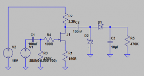
There you go, this sims to 0-10V DC output with 0-1V peak AC input.
I wanted to make it educational so you don't just copy the circuuit, but also learn from it 🙂 Since this is tube section of the forum I deliberately picked JFET transistor which behaves much like pentode in package that looks like triode without heating (it could just as well have been a BJT, as in your original circuit).
See, building a tube circuit would be no different - first pick a loadline (R2 versus supply voltage), then set cathode (in this case source) bias (with R1). I hope you'll try to figure out how it works and delve into tubes afterwards 😀
Few notes:
1: Take any common small signal JFET, say 2N5484 or J310 or something along these lines, whatever your local store stocks and is cheapest 🙂 You'll be experimenting a bit with R1 and R2 with real life transistor because it characteristics can vary significantly even among transistors of same type (don't go under 50R with R1 though just in case).
2: D1 and D2 can be any small signal schottky diodes (or if you happened to have some germanium diodes at hand ...), such as BAT48 etc.
3: R5 is not really a part of this circuit, it is the grid resistor of first stage of your EM87.
4: Values of R3, R4 and all the capacitors are just examples, if you have parts of different values at hand, feel free to change them, they won't affect the circuit much.
5: You might need to change the value of C3 significantly, depending on how responsive you want your level indicator to be (larger capacitor = slower, more stable response, smaller capacitor = faster response).
6: Last, but most important: you must not connect ground of this circuit to ground of EM87 even though both are called "ground". Connect supply voltage rail of this circuit to EM87's circuit ground in order for output to be negative as far as tube's input is concerned (-10V to 0V). Voltage at the grid of EM87 should not go positive with respect to the cathode, ever.
Attachments
Ok I am hoping I have this correct now...
I changed the value of R1 in your schematic to 56ohm.
This was to raise the gain as the input to the circuit is 1v peak to peak so it is half of what you had simulated.
I have been reading through some JFET basics. I will have another look at it when I get home as I do not have my notes on me.
I assume the gain is mostly controlled by the ratio of R2 and R1?
Below is the updated schematic.
I am not 100% sure if I can rectify the AC like I am to get the 16VDC.
Or is the voltage double necessary?
Also you will see that the I have called the 16VDC's ground GND1. The only other place that is connected is the the ground for the JFET amp.
Hopefully I understood you correctly and I have connected the 16V to the GND below the resistor on pin3 of the tubes.
Thanks
I changed the value of R1 in your schematic to 56ohm.
This was to raise the gain as the input to the circuit is 1v peak to peak so it is half of what you had simulated.
I have been reading through some JFET basics. I will have another look at it when I get home as I do not have my notes on me.
I assume the gain is mostly controlled by the ratio of R2 and R1?
Below is the updated schematic.
I am not 100% sure if I can rectify the AC like I am to get the 16VDC.
Or is the voltage double necessary?
Also you will see that the I have called the 16VDC's ground GND1. The only other place that is connected is the the ground for the JFET amp.
Hopefully I understood you correctly and I have connected the 16V to the GND below the resistor on pin3 of the tubes.
An externally hosted image should be here but it was not working when we last tested it.
Thanks
I to want to know how this worked out ReflexSa, as I would like to do soemthing similar.
Did you live through the experience, does it work?
I also got to say that there are some very clever people on this site supporting the rest of us. Make one feel a little inadequate.
Tony
Did you live through the experience, does it work?
I also got to say that there are some very clever people on this site supporting the rest of us. Make one feel a little inadequate.
Tony
- Status
- Not open for further replies.
- Home
- Amplifiers
- Tubes / Valves
- Problems with EM87 stereo level indicator for computer line out