Hi,
I built this schematics for a friend of mine but have some problems with it... unfortunately I can´t contact the "designer" of it any more.
It just worked fine on +/-45V DC (the author said, that he runs it at this voltage too).
I had 8 Ohm speakers (different ones, a subwoofer and a 3-way system - not at the same time) connected to it. It run some hours at some days with really big power!All just worked perfect and sounded well.
Then when running (at low power) it just blew... I fixed it and added a few modifications, but on the other day when turning on it blew again...😡
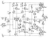
So, is this circuit designed well or is there a misdesign in there? What changes should be made?
I´m sorry for the bad circuit´s image, but I only have this one... the printed circuit is the original from the author. The painted additional circuits was added by me when repairing it (just some caps and resitors to prevent oscillations).
I built this schematics for a friend of mine but have some problems with it... unfortunately I can´t contact the "designer" of it any more.
It just worked fine on +/-45V DC (the author said, that he runs it at this voltage too).
I had 8 Ohm speakers (different ones, a subwoofer and a 3-way system - not at the same time) connected to it. It run some hours at some days with really big power!All just worked perfect and sounded well.
Then when running (at low power) it just blew... I fixed it and added a few modifications, but on the other day when turning on it blew again...😡
So, is this circuit designed well or is there a misdesign in there? What changes should be made?
I´m sorry for the bad circuit´s image, but I only have this one... the printed circuit is the original from the author. The painted additional circuits was added by me when repairing it (just some caps and resitors to prevent oscillations).
Attachments
transistors may dissipate more heat playing at medium volume than with full volume...
maybe this could be the reason??
how large are your heatsinks? which parts did blow??
best regards,
HB.
maybe this could be the reason??
how large are your heatsinks? which parts did blow??
best regards,
HB.
hugobross said:transistors may dissipate more heat playing at medium volume than with full volume...
maybe this could be the reason??
how large are your heatsinks? which parts did blow??
Heatsink is about 15*20*3 cm with ventilator mounted on it for both channels. I know it could/should be larger - but when playing at full power for some time it just became lukewarm at all! Unfortunately the case of the amp isn´t very big, so I had to use this heatsink and leave the case open at the upperside!
I don´t think it´s a heat-problem - but I don´t know. A friend of mine used the amp at low power (he said) and he wasn´t in the room, when it blew...
There were some transistors blown. I don´t know exactly which ones - it´s some time ago...I try to find out again.
For sure the BD249/250 were blown, but some others too...so this would indicate that it was no heat-problem, am I right?
In your opinion, is the circuit designed well? Is it worth a try again or should I make changes...
Something I forgot about the circuit:
The shortening-protection wasn´t dimensioned correct - the author told me.
He said to use BD139/140 for it instead of the BC546/556. So I replaced them.
The shortening-protection wasn´t dimensioned correct - the author told me.
He said to use BD139/140 for it instead of the BC546/556. So I replaced them.
It seems to me that nothing is limiting the bandwidth on the higher frequencies. This might lead to oscillation which can easily destroy output transistors. 1kohm resistor in series with C2 in the input and a 1nF cap in parallel with R1 should do the trick at the input. Also I would put 100-150pF cap parallel with R15 in the feedback.
I'm no audio amplifier designer, these are just things I've seen in other designs.
Regards, rMa
I'm no audio amplifier designer, these are just things I've seen in other designs.
Regards, rMa
- Status
- Not open for further replies.