Hello All
I have a problem on a Chinese amplifier which uses 2SC5200 and 2SA1943 transistors the final transistors were purchased from Farnell and are of the same category of HFE (o) the amplifier works but the loudspeaker safety trips as soon as the we push the volume I try to cool the input transistors but nothing changes. Does the problem come from the too spartan loudspeaker security or is it possible that the amplifier has a breakdown? I wired 2 modules the 2 do the same thing. Thanks for your help.


I have a problem on a Chinese amplifier which uses 2SC5200 and 2SA1943 transistors the final transistors were purchased from Farnell and are of the same category of HFE (o) the amplifier works but the loudspeaker safety trips as soon as the we push the volume I try to cool the input transistors but nothing changes. Does the problem come from the too spartan loudspeaker security or is it possible that the amplifier has a breakdown? I wired 2 modules the 2 do the same thing. Thanks for your help.

hi standard mica and silicone thermal paste. i dont think that was a thermal proble because the problem was present when the amplifier is cold!
Hi all
I removed the 20K ohm resistor from the loudspeaker protection and I was able to do my power tests. I manage to obtain a good signal without distortions of 100W on 4 ohms with a +- 32 V power supply. If there was a failure in the pre-amplifier stages, it would show on the power signal, right?

I removed the 20K ohm resistor from the loudspeaker protection and I was able to do my power tests. I manage to obtain a good signal without distortions of 100W on 4 ohms with a +- 32 V power supply. If there was a failure in the pre-amplifier stages, it would show on the power signal, right?
right the 20k link the output power amplifer with the speaker protection! Without signal at the input and no load on the output i measure +30mV DC. the strange thing was that the 2 modules that i have wired do the same. I dont understand
In principle, when this kind of phenomenon occurs, it is the pre-amplifier stages, in particular the transistors of the differential amps, which are in question, but even when cooling the pre-amp transistors with icing bomb, nothing changes.
Is it one protection ckt? if so, you should have two 20K, each summed at the protection input and the other ends going to the amp L & R outputs.
Look at the base of T2 to see if it gets turned on
Does your protection ckt have an AC presence detection?
I use that type of protection ckt, it is better to put a zener at the base of T3, in your case of a 12V supply use a ~5V1. I'll post an example of a better ckt
Look at the base of T2 to see if it gets turned on
Does your protection ckt have an AC presence detection?
I use that type of protection ckt, it is better to put a zener at the base of T3, in your case of a 12V supply use a ~5V1. I'll post an example of a better ckt
Attachments
Agree and add:
1) clamp your multimeter across 220uF cap , the one after 20k resistor: check whether DC appears there when you rise volume.
Sometimes even with pure Audio, which of course is AC, there is waveform asymmetry which protector "thinks" is DC
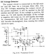
When that capacitor charges to + or - 0.65V, it will trigger T1 or T2.
2) worried by inconsistencies between what you write and what you show.
1) clamp your multimeter across 220uF cap , the one after 20k resistor: check whether DC appears there when you rise volume.
Sometimes even with pure Audio, which of course is AC, there is waveform asymmetry which protector "thinks" is DC
When that capacitor charges to + or - 0.65V, it will trigger T1 or T2.
2) worried by inconsistencies between what you write and what you show.
with a +- 32 V power supply{/quote]
BUT you show a car type SMPS which presumably is fed 12V DC from a car battery, and whose output is unspecified, but certainly way higher than +/- 32V or it can´t meet its "1000W" spec.
Also your power amp shows a pair terminals at the bottom of the picture labelled "12VAC"
Not sure where would you get 12VAC in a car.
Hello and thank you for your help.
In fact, I'm doing the preliminary tests with a current-limited lab power supply of +-32V. There is loudspeaker protection by the MONO modules! Indeed it may be missing a zener on the assembly, so my theory is that the problem comes from the protection of the loudspeaker rather than the amp.
Finally, the amp is designed to be powered by a DC/DC converter 12V DC to +- 80V DC, and there is an axillary 12V DC coming from the DC/DC converter see the photo of the kit. The 12VAC on the amp board is only used to power the speaker protection and fans. I will therefore use the 12 DC auxiliary for these functions.
Hoping to have clarified my words
Last edited:

1) clamp your multimeter across 220uF cap , the one after 20k resistor: check whether DC appears there when you rise volume.
Sometimes even with pure Audio, which of course is AC, there is waveform asymmetry which protector "thinks" is DC
When that capacitor charges to + or - 0.65V, it will trigger T1 or T2.
I have the impression that this is exactly what is happening, because the speaker security activation indicator LED lights up according to the audio level I send to the input.
So you are surely right. I will try the solution of the zener in the base of the protection relay driver transistor, to try. If the solution is not sustainable I can add an auxiliary loudspeaker protection circuit, or simply do without it!
Is the 220uF a bipolar electrolytic cap?
No there are 2 standads electrolytic cap mount in oposite serial polarity.
I think JMFahey and rsavas got it right because the loudspeaker security activation LED lights up according to the signal strength I inject at the input until the loudspeaker relay is triggered. The solution of adding a zener in the base of the switching transistor is surely the right method given that on the assembly from Pioneer there is this diode in addition, I will try this option if it works so much the better if not I would do without output DC safety device!Is the 220uF a bipolar electrolytic cap?
Your speaker protetcor is pretty useless, 'cause it solely detects positive voltages WRT ground. In addition, it rectifies AC voltages into positive DC voltages and trips the relay. You'd need something like in #12.
Best regards!
Best regards!
Yes I agree with you but given the use on loudspeakers permanently mounted and very powerful I do not think that protection is really necessary.Your speaker protetcor is pretty useless, 'cause it solely detects positive voltages WRT ground. In addition, it rectifies AC voltages into positive DC voltages and trips the relay. You'd need something like in #12.
Best regards!
- Home
- Amplifiers
- Solid State
- Problems on Chinese Power amplifer Module