I'm trying to build amp from attachment but normally I have problems...
When I first connected the amp voltage drop across 0.22resistors were 0V... I was adviced to remove output transistors, remove 220R resistor that is connecting the emiters of drivers and install 120R res. to the emiters of drivers, so now the drivers are output tranzistors with 120R emiter resistors... man I'm complicating...
So, now I have ~4.5V drop on those resistors no matter in what position trimmer is!
Any idea where to start searching for error?? I checked all the components more than once... I also made another board but with same results 🙁(
Attachments
What about those people that gave you that "advice", where are they now? Ran away?😉
I would advice to built it up in the original configuration, and then apply a revolutionary concept: measure!
There appears nothing wrong with the schematic. I promise you that once you start measuring the DC conditions in the amp, the error will quickly become clear. Especially with 0V across the Re, that's much easier than a burning output stage!
Jan Didden
let's insert back the outpot transistors.
now in the Vbe multiplier remove the 4,7K resistor, and use and change the 1,8K to 1K. use a trimpot rated 1K.
then heat up the amp, and let's try to get a normal bias.
now in the Vbe multiplier remove the 4,7K resistor, and use and change the 1,8K to 1K. use a trimpot rated 1K.
then heat up the amp, and let's try to get a normal bias.
Hi add a link from pot wiper to upper end of 4k7, just in case the pot fails open cicuit.
Add some local decouling to the output cap ends of the supply rails and some smaller caps to the driver ends of same rails. Connect all decoupling grounds to the power ground not the signal ground. Use insulated wire point to point (P2P)
Add some local decouling to the output cap ends of the supply rails and some smaller caps to the driver ends of same rails. Connect all decoupling grounds to the power ground not the signal ground. Use insulated wire point to point (P2P)
First of all, thanx for answering so fast!!
eld:
about that 4k7 res, after I remove it, do I have to short two holes he's been in?
First thing I'll do is get some sleep...I'm working on this amp all day (today I printed the PCB on paper), drilled the holes, assambled all, and realised that it's not functioning 🙁
SO I'm a bit frustrated...and I'm also frustrated for my bad english🙂
it's harder over the internet...janneman said:What about those people that gave you that "advice", where are they now? Ran away?😉
eld:
about that 4k7 res, after I remove it, do I have to short two holes he's been in?
First thing I'll do is get some sleep...I'm working on this amp all day (today I printed the PCB on paper), drilled the holes, assambled all, and realised that it's not functioning 🙁
SO I'm a bit frustrated...and I'm also frustrated for my bad english🙂
instead of going to sleep I made a few of those changes you adviced me to...
I short-circuted the 4k7 resistor, replaced 1k8 with 1k and replaced trimmer to 2k5 (i don't have 1k right now...)
So, ,voltage drop across Re is stil 3.7V min and ~4.3V when trimmer is at full left...
PS.
Andrew, I didn't quite understood your post, my english terminology is not so good...
I short-circuted the 4k7 resistor, replaced 1k8 with 1k and replaced trimmer to 2k5 (i don't have 1k right now...)
So, ,voltage drop across Re is stil 3.7V min and ~4.3V when trimmer is at full left...
PS.
Andrew, I didn't quite understood your post, my english terminology is not so good...
Bok,
Najcesca greska koju sam vidjao u ovakvim dizajnima su pogresno okrenuti tranzistori MJE340 i 350 (odnosno BD139/140). Kad ga gledas sa strane natpisa redoslijed je slijeva nadesno E-C-B, dok je uobicajeno B-C-E. Mozda se ta greska i tebi potkrala.
Za daljnje pronalazenje greske bilo bi dobro da izmjeris napon C-E na tranzistoru BC556 pri krajnjim tockama trimera.
First, check the polarity of the driver transistors.
Second, measure voltage across C-E pins of the transistor BC556 at the end points of the trimmer.
Regards,
Milan
Thanx I will!
Instead of using MJE340/50 I used MJe15030/31 wich have pinout B C E when viewed from front...
Instead of using MJE340/50 I used MJe15030/31 wich have pinout B C E when viewed from front...
Ok, ,here it is...
when trimmer is full right Ur=3.7V and Uce=0.69V, and when full left then Ur=4.3V, and Uce=2.3V
PS.
I still have instaled only driver transistors and 120R emiter resistors... Dr. Jagodic, the guy that designed this amp adviced me to do that temporary until I fix the problem...
when trimmer is full right Ur=3.7V and Uce=0.69V, and when full left then Ur=4.3V, and Uce=2.3V
PS.
I still have instaled only driver transistors and 120R emiter resistors... Dr. Jagodic, the guy that designed this amp adviced me to do that temporary until I fix the problem...
Mlaen said:..... and Uce=2.3V ...
Correct readings for Uce=2.3V
Attachments
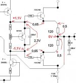
I'll do other measurings now but before that...
I saw you calculated 0.5V across 120R resistors... I had 0.5V drop on them when I first connected the amp after the mod that edl adviced but when I increase trimmer a bit voltage increases to 3.7V and after that I can't lower it back to 0.5V...
I saw you calculated 0.5V across 120R resistors... I had 0.5V drop on them when I first connected the amp after the mod that edl adviced but when I increase trimmer a bit voltage increases to 3.7V and after that I can't lower it back to 0.5V...
Hi Mlaen !
About the topology you are building, i can assure you that it
works "perfect". If you follow the voltages from "moamps",
everything is fine...
My latest amp uses a very similar topology and shows amazing
quality and reliability !
Mike
About the topology you are building, i can assure you that it
works "perfect". If you follow the voltages from "moamps",
everything is fine...
My latest amp uses a very similar topology and shows amazing
quality and reliability !
Mike
I have +1.1V just like you calculated, but on second transistor i have -0.9V...
DRIVERS -> Ube insted of 0.65V is ~3.1V
And where I have ~7mV on output...
MikeB:
Yes, many people build this amp from the first shot and are very pleased with it, but for me, it's impossible to build an amp from the first shot!
Thanx for the encourage!
DRIVERS -> Ube insted of 0.65V is ~3.1V
And where I have ~7mV on output...
MikeB:
Yes, many people build this amp from the first shot and are very pleased with it, but for me, it's impossible to build an amp from the first shot!
Thanx for the encourage!
The fact that these voltages are not perfectly symetrical, shows
that the feedback tries to compensate DC-offset of 100mv,
nothing to worry about. (For now)
It sounds like one of your drivertransistors is defect, a vbe of
3.1v is only possible with reversebias. Have you checked if the
collectors of these drivers are connected correctly ?
Have you verified powersupply ?
Collectors are connected correctly! And PS is OK!
I'll try to change transistors...after school...
I'll try to change transistors...after school...
Mlaen said:[snip]DRIVERS -> Ube insted of 0.65V is ~3.1V
And where I have ~7mV on output...
[snip]
Mlaen,
What exactly do you mean by this? Can you be a bit more specific? I assume you have not connected the output pair? Did you connect the base & emitter pads of the output pair for this testing?
Jan Didden
output voltage is 7mV instead 0V....
I did not yet connected the output pair....first I'll try to get all the voltages Milan calculated... I just bought a new pair of drivers so I'll see...
Milan:
Just to be sure...
Did you made the calculations by the original schematics or afetr the edl's mod?
I did not yet connected the output pair....first I'll try to get all the voltages Milan calculated... I just bought a new pair of drivers so I'll see...
Milan:
Just to be sure...
Did you made the calculations by the original schematics or afetr the edl's mod?
Mlaen said:Did you made the calculations by the original schematics or afetr the edl's mod?
After.
You've mail.
Milan
Mlaen said:output voltage is 7mV instead 0V....
Just a hint... 7mv output is ~0v !
Most amps have more dc-offset...
Mike
Now I'm pissed! 🙁(
I replaced drivers (MJE15030/31) with new ones...and I stilll have Ube=3.1V on NPN type and 3.3V on NPN type!!
The only thing that changed is voltage on emiter resistors increases faster than before (before max volatge vas ~4.3V now I have that voltage when I increase trimmer value just a bit...)...still cannot decrease voltage below 3.3V🙁
any more ideas?
- Status
- Not open for further replies.
- Home
- Amplifiers
- Solid State
- Problems, again, with building the amp...