Hello
This is Sreenath, and I am currently facing a problem where I build my own amplifier based on Tpa3110 - Power Limiter, (as on Datasheet). But somehow after all soldering when I connect the amp to VCC 14V, there is no sound and the speakers does not provide any Output.
Please give me a solution what is wrong with it.
Thank You
Sreenath C.
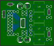
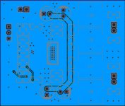
**Schematic Diagram and Pcb Layout Attached.**
This is Sreenath, and I am currently facing a problem where I build my own amplifier based on Tpa3110 - Power Limiter, (as on Datasheet). But somehow after all soldering when I connect the amp to VCC 14V, there is no sound and the speakers does not provide any Output.
Please give me a solution what is wrong with it.
Thank You
Sreenath C.
**Schematic Diagram and Pcb Layout Attached.**
Attachments
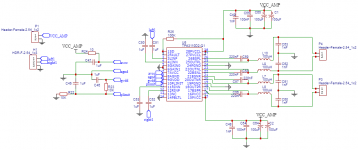
Check supply AVCC, should be close 14V
Check supply GVDD should be 7V
Check pin 2, if low amp is in fault condition.
Check your solder joints re work them one by one with flux and braid, schematic looks ok, it the same as the one in the datasheet, this should work !
Rgds
Check supply GVDD should be 7V
Check pin 2, if low amp is in fault condition.
Check your solder joints re work them one by one with flux and braid, schematic looks ok, it the same as the one in the datasheet, this should work !
Rgds
Hello AIM65
Thanks for the response.
Yeah Actually I have measured the values and I am Getting -
AVCC - 14V
GVDD - 5.8V
PIN 2 & 1 are connected to 100k, I am getting about 1.65v here.
I have already soldered them thrice but there is this same Problem, I think I wanna do it again to make sure the solder sits.
Thank You!
Sreenath C.
Hi,
This is weird, schematics is so simple…if solder joints are ok the chip is the best candidate for being a faulty part, but some test remains feasible.
Is your voltmeter a digital one or analog? Analog ones have low input impedance that could produce wrong results when measuring high impedance source, which is the case with pin 1&2 with their 100k pull-up.
What do you have connected on outputs? Don’t leave them open.
Is the pad well soldered on the ground plane, underneath the chip?
AVCC is ok, but GVDD is wrong, this is an output of a 6.9V internal regulator, you should have close to 6.9V. Easy test: remove C46 and R23 and check GVDD again, if ok change them.
As GVDD is wrong we can’t expect the chip to operate properly. Voltage on is PIN 1&2 very bad : Pin 2 is open drain output, voltage should be close 0 or close VCC_AMP, currently it's within the noise area of pin 1 input which thresholds are 0.8V for L and 2V for H. Easy test : ensure that R25 is really 100k.
Other test, cut the track between pin 1 and pin 2 in order to leave pin 2 open. Test and measure again. This last test has to be made with a current limiting power supply, because it disable the self-protection of the chip.
Rgds
Hey Aim65
Thanks for the detailed suggestion.
Actually it was my fault that the input pins were not soldered properly, maybe that was the problem.
But now after soldering, everything is back to normal and can play sound.
So the new problem that I am facing, is that while its playing music the chips gets very hot maybe around 60~80°C, Can you tell me why is that so? And the other problem is that the music is very damped and distorted, doesn't sound like 15w, but like 5W. I think that might be due to the 100uH Inductor.
Thank You
Sreenath C.
Hi,
you should try to read datasheet;§9.3.4 give you some clues about output power.
Try removing R22, that will enable full power, within the limits of your power supply.
About 100uH, the only thing I know is written in the DS : 66uH for 8 Ohms, 47uH for 6 Ohms and 33uH for 4 Ohms.
Rgds
you should try to read datasheet;§9.3.4 give you some clues about output power.
Try removing R22, that will enable full power, within the limits of your power supply.
About 100uH, the only thing I know is written in the DS : 66uH for 8 Ohms, 47uH for 6 Ohms and 33uH for 4 Ohms.
Rgds