First, let me thank everyone, but esp. Motherone, Roger, George, Panomaniac, and Panelhead for the detailed analysis and suggestions for modding.
This is my first electrical mod, so clearly at risk for a SNAFU.
I've done a test set up with the stock board in a simple rebox, to establish a baseline performance. I'm waiting on parts, esp. an Alps pot, so I'm using alligators instead of soldering the connections, as well as the stock pot. And therein lies the problem.
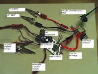
As shown in the picture, I've sliced into the pot, with the connections as labeled. I'm leaving the left three wires from the audio connection cut, as my understanding is these (left, right inputs, ground) are bypassed to the pot.
The problem is: on power up I get this sputtering, machine gun like sound.
A couple of additional facts:
1) I'm using a 12v regulated powersupply.
2) When I first wired it up, I spliced the input leads according to Motherone's listing of leads:
V = switch 12volt
out + = switch 12volt in
Ro = to volume from right channel
Lo = to volume from left channel
G = ground
Li = from volume control to amp left channel
Ri = from volume control to amp left channel.
When I did this, I got no sound out at all with power on, but actually a very faint output from my speaker with the power off (and the pot did work to attenuate the volume).
So: where did I miswire?
Thanks in advance,
Bob
This is my first electrical mod, so clearly at risk for a SNAFU.
I've done a test set up with the stock board in a simple rebox, to establish a baseline performance. I'm waiting on parts, esp. an Alps pot, so I'm using alligators instead of soldering the connections, as well as the stock pot. And therein lies the problem.
As shown in the picture, I've sliced into the pot, with the connections as labeled. I'm leaving the left three wires from the audio connection cut, as my understanding is these (left, right inputs, ground) are bypassed to the pot.
The problem is: on power up I get this sputtering, machine gun like sound.
A couple of additional facts:
1) I'm using a 12v regulated powersupply.
2) When I first wired it up, I spliced the input leads according to Motherone's listing of leads:
V = switch 12volt
out + = switch 12volt in
Ro = to volume from right channel
Lo = to volume from left channel
G = ground
Li = from volume control to amp left channel
Ri = from volume control to amp left channel.
When I did this, I got no sound out at all with power on, but actually a very faint output from my speaker with the power off (and the pot did work to attenuate the volume).
So: where did I miswire?
Thanks in advance,
Bob
Attachments
Hi, I don't know much but your first problem is you cut the ground wire between the cct and the pot,?
Also the 2 red wires to the pot are just the power swich, you can cut and join these together near the main board and switch at the supply(The alps will not have a connection for these. ) Good Luck...
Also the 2 red wires to the pot are just the power swich, you can cut and join these together near the main board and switch at the supply(The alps will not have a connection for these. ) Good Luck...
Thanks.
Re: the ground, so just splice the ground from the inputs into this lead (once reconnected?).
Re: the ground, so just splice the ground from the inputs into this lead (once reconnected?).
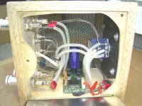
I have attatched a picture of one of my amps. I hope you can see how to connect the ALPS pot. A have soldered the the L, R and G pot wires to the bottom of the board. The G wire goes to the pot and the input grounds.
Good Luck Barry.
Good Luck Barry.
If you're using a direct wired volume control (i.e. wiring from your input RCAs directly to the potentiometer), you don't need to worry about Ro/Lo. Those just attach to the 1/8" jack on the board.
To wire up an alps, with the shaft facing to the right and the pins facing you, it goes as follows:
Top pair: Ground
Middle Pair: Output
Bottom Pair: Input
If you're still having problems after this, please try to post a close-up picture of the board + alps.
Good luck!
To wire up an alps, with the shaft facing to the right and the pins facing you, it goes as follows:
Top pair: Ground
Middle Pair: Output
Bottom Pair: Input
If you're still having problems after this, please try to post a close-up picture of the board + alps.
Good luck!
Thanks.
I've put in the 2200uf output cap. That cleared up some high end grittiness and silibance.
Now onto the input caps.
Bob
I've put in the 2200uf output cap. That cleared up some high end grittiness and silibance.
Now onto the input caps.
Bob
Do you mean the PSU bypass cap? The onboard electrolytic (the one that sits between the 4 inductors) is just a bypass cap for the power rail.
Most people say it improves the bass by increasing it. 2200uF is fairly large -- did you manage to fit it comfortably onboard?
Most people say it improves the bass by increasing it. 2200uF is fairly large -- did you manage to fit it comfortably onboard?
Yes, meant the PSU bypass. Mounted it on the bottom of the board for room.
No problem with bass from the beginning, as I'm used Def Tech towers with built in subs.
No problem with bass from the beginning, as I'm used Def Tech towers with built in subs.
Ah, which Definitives? I've always meant to give 'em a listen.
Glad to hear the mods are moving along!
Glad to hear the mods are moving along!
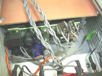
The Cap in my picture that you asked about is a no-name I got out of an old Marantz Cd player, it is a 6800 -16V size, on long legs (probably not ideal) so it fits on top of the board.
On another amp I used a 1000 -16V from the same CD player. I think this is the largest size you can have in the original space.
I have attatched a pic which also shows the Black-Gate input Caps (2.2), negative to the pot according to the Tripath dia'.
I also only use a low cost 10k Pot with a good 10k resistor in Shunt mode.
We all have our own ways of mod'ing these little fun Amps with help from other people on this forum.
Ps , I have had no trouble running a pair of Wharfedale Evo 20's off these Amps, good bass and no clipping.. Good luck to all.
Attachments
Thanks audio1st for the photo.
Motherone: I'm using the Def Tech 2006s.
http://www.definitivetech.com/reviews/BP2006TLSV.pdf
Motherone: I'm using the Def Tech 2006s.
http://www.definitivetech.com/reviews/BP2006TLSV.pdf
- Status
- Not open for further replies.
- Home
- Amplifiers
- Class D
- Problem with T-amp Mods