I took a quick look at the schematic and it looks like it is pretty easy to pull the "amp" boards of the system. I'd pull all that and see if the preamp side is working ok and not faulting. So if the preamp is alive (voltages look ok at B+/B- and supply voltages for preamp are good, I'd put in the amp boards one channel at a time to isolate. All the while keeping the bulb protection in. The bulb should go very dim if all is good. Initially bright as the supply caps come up, but then so dim you may not see the filament lit.
That sounds like a good way to maybe isolate the problem faster. Would you be able to give more details on how to pull the amp boards off the system? Thanks.
If I am reading the schematic correctly, pulling connectors K1A, K2A, K3A, K4A will disconnect the driver part of the amps. It looks like B+/- is still connected to the EF's though. Maybe a jumper on the main board might disconnect those if you are lucky. Worst case, pull all the Q's off the board and test them with a tran tester. Quite a few though, 18 would need to be pulled. Do you have a tran tester? They are pretty inexpensive.
A transistor tester? No, but I have a DMM, will that not be sufficient to test transistors? Thanks for the info. I'll have to check and see how boards are connected, not sure if they can be pulled off easily. Sorry for my lack of knowledge here, but what do you mean by "It looks like B+/- is still connected to the EF's"?
I picked up an inexpensive DMM the other day as an extra, I think it was around 10 dollars and had a transistor tester on it. The EF's are "Emitter followers". Note in the output part there is a pair of transistors directly connected to the output on their emitter. Then their base is connected to the emitter of the device to the left on the schematic. Then the middle transistor's base is connected to the emitter of the previous device. And then those base's are connected to a transistor which sets the bias. All of those emitter followers have their collectors connected to B+/B-. That triplet of emitter followers provides current gain to drive the low resistance speakers.
It is very likely one or more of those devices has been fried based on your earlier comments, and so a tester is going to be very useful. The inexpensive testers on DMM's usually test only beta, no leakage or breakdown voltage testing.
It is very likely one or more of those devices has been fried based on your earlier comments, and so a tester is going to be very useful. The inexpensive testers on DMM's usually test only beta, no leakage or breakdown voltage testing.
So I finally had time again to look at the amp.
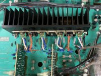
The two separate PCBs, X-1294D03 and X-1294D04, can indeed be pulled off at K1A+K3A and K2A+K4A respectively. I can't find any jumpers on the main board that can disconnect B+/- from the EF’s. Would you still recommend disconnecting the two boards?
You say that worst case I’d need to pull 18 transistors and test them. Are you referring to Q617-634? How do I go about testing them the correct way? I assume I need them off the board in order to test?
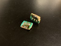
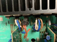
Btw when I corrected the PNP/NPN mistake pointed out by Lojzek, I removed the small prints connecting the four transistors, Q623-626, to the main board. They looked burned/damaged, so I decided to remove them, and then connect the cables directly to the transistors. I guess that’s okay to do?
See attached photos.
Again, thanks a lot for your help!
The two separate PCBs, X-1294D03 and X-1294D04, can indeed be pulled off at K1A+K3A and K2A+K4A respectively. I can't find any jumpers on the main board that can disconnect B+/- from the EF’s. Would you still recommend disconnecting the two boards?
You say that worst case I’d need to pull 18 transistors and test them. Are you referring to Q617-634? How do I go about testing them the correct way? I assume I need them off the board in order to test?
Btw when I corrected the PNP/NPN mistake pointed out by Lojzek, I removed the small prints connecting the four transistors, Q623-626, to the main board. They looked burned/damaged, so I decided to remove them, and then connect the cables directly to the transistors. I guess that’s okay to do?
See attached photos.
Again, thanks a lot for your help!