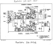
I have one of these little solidstate realistic sa-100C amplifiers. It has distorted sound on both channels. Kind of like the input is being over driven. Thats what it sounds like. I replaced the power supply cap, cleaned all the controls, replaced the cap in the signal path. There is no voltages on the schematic and I can find no inormation anywhere that has voltages listed. Being that it is dostorted the same on both channels is what has me stumped. There is nothing to the power supply and I replaced the cap. Any help as to where to look would be appreciated.
Jeff
Jeff
Attachments
Try cleaning the contacts on the speaker relay, or replace it. The contacts often corrode or get dirty.
Especially if the headphone jack output sounds ok.
Especially if the headphone jack output sounds ok.
If it has distorted sound on both channel regardless of volume.
First make sure the distortion actually is created in the final amp. I you cannot measure that, connect some kind of amplifier or recorder to the jonction of VR3 and R10A. Sound should be clear.
Check supply voltage on C5. Should be 12-15V.
Check supply voltage on collector of Q5A. Should be 25-30 V
Check voltage on junction of C15A and R23A. Should be about half the supply voltage.
Check current through collector of Q5A. Must be 20-50 mA
If the distortion start at medium level, check C13A. If this capacitor has lost capacity half of the output signal gets severely limited when played higher than low level.
With no voltages given we have to estimate. The speaker coupling cap is 16v and so that sets a limit on the supply of no more than 32 volts. I would guess it all runs on something more like a 25 volt rail.
Measure the voltage on that 1A fuse and then measure the voltage on the + end of each speaker coupling cap. It should be around half the measured supply voltage.
The voltages to the FET preamp look shared. Check voltages on C5 and C12. Lets guess at 12 volts on C5. If low the resistors feeding it could be suspect, the 1.2k and the 2.2k up at the top.

Thank you, all of you so much! Ihave a ton of stuff to try and I am certain I will find my problem. Thanks again
If it has distorted sound on both channel regardless of volume.
First make sure the distortion actually is created in the final amp. I you cannot measure that, connect some kind of amplifier or recorder to the jonction of VR3 and R10A. Sound should be clear.
Check supply voltage on C5. Should be 12-15V.
Check supply voltage on collector of Q5A. Should be 25-30 V
Check voltage on junction of C15A and R23A. Should be about half the supply voltage.
Check current through collector of Q5A. Must be 20-50 mA
If the distortion start at medium level, check C13A. If this capacitor has lost capacity half of the output signal gets severely limited when played higher than l
I checked the voltage at the filter cap and its 9 volts and change.Voltage on Q5A collector is 6 volts. I replaced the diodes and the filter cap but no change. All it could be is a bad transformer isn't it?
Does the voltage come up if you remove the fuse? Sounds like something is dragging it down. If the trafo were bad it would either not give any output at all, or be getting hot and buzzing.
Very unlikely.All it could be is a bad transformer isn't it?
Put your meter on AC volts and measure from ground to each anode of the rectifier diodes (the end that goes to the transformer). The AC voltage should be steady and around 18 volts AC.
I have once come across a fuse (not the fuseholder) that did something like this. The wire in the fuse was only just touching the endcap.
It took me 12 hours to understand the meaning of "It was clear on R10A". Now I understand the sound was clear and undistorted on R10A.Oh and it was clear on R10A
Which is strange. Because if the collector of Q5A is at 6V, the voltage on C5 can't be the designed voltage. It is possible the signal level is so low on that point the low voltage does not impair the signal yet.
Too bad you did not include the measured voltage on C5. We are not clairvoyant at the other side of the forum, let alone we can put the probes in your circuit.
Replacing the diodes and capacitor? Why? Were they faulty?
As Mooly asked did you measure the AC voltage? And after that, follow the DC voltage step by step until you reach Q5A. That can't be to difficult?
Ok the voltage on C5 I did list. Its the filter cap and its 9 volts. I checked in AC mode at the rectifing diodes and the voltage is like 7. I un soldered the fuse and no change. I replaced the cap and diodes because it was fast and easy and cheap and now I know its good.
Did somebody put a 220V primary transformer in there? If you got double that, it would at least make sense. A transformer’s output goes low for two reasons. 1. Shorted turns, but that’s associated with overheating. 2. Being fed too low input voltage. Does it stay stone cold if left plugged in without the fuse (therefore no load) for an hour? If the primary voltage really is wrong you won’t even get the normal temperature rise as the magnetizing current will be low. If there is a short between turns in the primary, it will get hot. Hotter than normal.
I measured the ac again I did it wrong the first time. I put a lead on each diode and I am getting 15vac
I checked R11 and R18 and they are both correct and good
I checked R11 and R18 and they are both correct and good
It’s almost inconceivable (to me) that the supply really IS supposed to be 9 VDC. If it really is, it would be ridiculously easy to overdrive, and normal output power would be well under 1 watt. If you turn it WAY down, with hardly any volume at all, does it clean up and sound normal? It could be you’re just expecting too much out of it.
I found this... now is this real watts or peak total max music power with the wind behind it 😉

If its real watts then that is just over 6 volts rms output needing around a 24 volt or so supply to achieve that.
If you have 15 volt AC going into the diodes then you must see about 21 volts DC across C17
Voltage across C5 must be lower than the marked voltage of the cap (16 volt) so 9 volts could be fine.
So is one channel OK and one not ???
If its real watts then that is just over 6 volts rms output needing around a 24 volt or so supply to achieve that.
I measured the ac again I did it wrong the first time. I put a lead on each diode and I am getting 15vac
I checked R11 and R18 and they are both correct and good
If you have 15 volt AC going into the diodes then you must see about 21 volts DC across C17
Voltage across C5 must be lower than the marked voltage of the cap (16 volt) so 9 volts could be fine.
So is one channel OK and one not ???
HOW did you measure. Black on kathode D2 and red on kathode D3?I measured the ac again I did it wrong the first time. I put a lead on each diode and I am getting 15vac
Or black on kathode D2 and red on anode D2?
Put your black lead on ground and measure DC red lead on kathode D2/D3 junction.
If this is 22V continue with below.
Put your meter on AC. Yes AC lowest range.
Measure AC. Black lead on ground. Red lead on junction D2/D3
Report back.
To save time.
Desolder the kathodes of D2 and D3. That is the side with the band mark on the diode. The side which is connected to C17.
Leave the diodes connected to the transformer side.
Meter on DC. Black lead to ground.
Red lead to kathode of each D2 and D3
What do you measure.
This is incomplete information.I checked R11 and R18 and they are both correct and good
How did you check them? Resistance? In-circuit? Out-circuit?
Correct way: Meter on DC black lead to ground.
Red lead to one side of R11. Then red lead to other side of R11.
Same for R18
Now you have 4 voltages.
What are those.
Next time you measure something "correct and good" please tell us what you measured and how you measured.
Back in those days Radio Shack didn’t outright lie about power ratings. Their receivers put out the stated power. That power supply voltage should be around 20-25 volts, about right for a TO-126 pair in EF1. If it were only a 1 watt amplifier, they would have used the giant TO-92’s.
Maybe the output transistors are bad, dragging down the supply voltage. Test them out of circuit? Throw in a BD139/140 pair for $***’s and giggles? Higher current type would sound better with less beta droop, but those are often on hand…..
Maybe the output transistors are bad, dragging down the supply voltage. Test them out of circuit? Throw in a BD139/140 pair for $***’s and giggles? Higher current type would sound better with less beta droop, but those are often on hand…..
Oh my I just checked out the datasheet for the 2SC496 transistor. Max Ic of 1A ?? What collector voltage in a class AB amplifier would be appropriate for such transistors? It looks like they connected the driver stage to the speaker output and forgot to include the final stage. LOL.
- Home
- Amplifiers
- Solid State
- problem with Realistic SA-100C