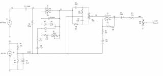
Hi Guys,
I am not an electric or electronic engineer, I am just a hobbyist but I have designed a very basic guitar preamp with a clipping stage, BMP tone stack and recovery stage. The circuit is very simple, I have simulated it with LTSpice and everything works as expected in the simulation.

But it does not work when breadboarded. I have tried everything, I have changed every single component, power supply, protoboard, It just not work. I have started from the begining many times.... no success. An initial DC analysis show me that DC voltages are correct in the correct places, but no sound goes to the output. I suspect there is some error in the design, but LTSpice did not catch it.
Can anyone give me some advice?
I am not an electric or electronic engineer, I am just a hobbyist but I have designed a very basic guitar preamp with a clipping stage, BMP tone stack and recovery stage. The circuit is very simple, I have simulated it with LTSpice and everything works as expected in the simulation.

But it does not work when breadboarded. I have tried everything, I have changed every single component, power supply, protoboard, It just not work. I have started from the begining many times.... no success. An initial DC analysis show me that DC voltages are correct in the correct places, but no sound goes to the output. I suspect there is some error in the design, but LTSpice did not catch it.
Can anyone give me some advice?
Can anyone give me some advice?
Not clear from your description, did you measure the actual DC at the op amp outputs
wrt ground? It should be 6V, or Vcc/2. If that is ok, then try removing the diodes.
Are the electrolytics each connected in the right polarity?
Also try removing the tone control, and connecting Vc directly to Vd.
Last edited:
Hi Rayma,
Thanks for your interest.
Yes the opAmp output is Vcc/2, I have also tried without diodes in the first stage. Do you think the circuit is in general well designed? I suspect there must be an error but my knowledge is very limited in this area.
Thanks for your interest.
Yes the opAmp output is Vcc/2, I have also tried without diodes in the first stage. Do you think the circuit is in general well designed? I suspect there must be an error but my knowledge is very limited in this area.
Your pinout is wrong, unsure how/why simulation wouldn't complain.
a) state which OP Amps you are using
b) download and check datasheet
c) post *verified actual* (made with pencil and paper) schematic of what you * actually* built, not a screen capture or what simulation *was told* you built.
a) state which OP Amps you are using
b) download and check datasheet
c) post *verified actual* (made with pencil and paper) schematic of what you * actually* built, not a screen capture or what simulation *was told* you built.
Yes the opAmp output is Vcc/2, I have also tried without diodes in the first stage.
Do you get a waveform at Vc? If you lack a scope, just connect Vc through
the output coupling capacitor to listen.
Opamp pinouts are crazy in the schematic because the LTSpice Model number it this way. But The real circuit is using correct pinout. The OpAmp I am using is TL072.
3(+), 2(-), 1(out) for the first opamp and 5(+), 6(-), 7(out) for the second.
3(+), 2(-), 1(out) for the first opamp and 5(+), 6(-), 7(out) for the second.
Do you get a waveform at Vc? If you lack a scope, just connect Vc through
the output coupling capacitor to listen.
I don't have a scope. But i measured Vcc/2 at Vc and Ve
I don't have a scope. But i measured Vcc/2 at Vc and Ve
Ok, then disconnect the tone control circuit and directly connect the first and second stages.
Do you get sound now?
Opamp pinouts are crazy in the schematic because the LTSpice Model number it this way. But The real circuit is using correct pinout. The OpAmp I am using is TL072.
3(+), 2(-), 1(out) for the first opamp and 5(+), 6(-), 7(out) for the second.
And then 4(Ground) and 8(Vcc), right? Well, just to clarify.
If everything is assembled as shown - it should work.
And then 4(Ground) and 8(Vcc), right? Well, just to clarify.
If everything is assembled as shown - it should work.
Yes 4(gnd) and 8(vcc). I have checked everything more tan 10 times. I will start again from zero stage by stage....
Yes 4(gnd) and 8(vcc). I have checked everything more tan 10 times.
I will start again from zero stage by stage....
The IC pins are numbered ccw as viewed from the top, starting at the dot, right?
The IC pins are numbered ccw as viewed from the top, starting at the dot, right?
Of course. This is not my first project. Usually everything works at second try.... but this time there is something wrong with the design maybe. I will try again tomorrow but if it does not work I will change the circuit... maybe change the last stage for an inverting amplifier.
- Status
- Not open for further replies.
- Home
- Amplifiers
- Solid State
- Problem with preamp design