Totally understand, I've been in those shoes, but please consider looking up DIY O' scope interfaces to computer projects---you may be surprised that you can build an ok O' scope for use in audio just to trace your test (sine) signals---usually connect to sound card on computer for inexpensive ones.
Thanks Anducer,
That's amazing, I'm searching more to get more information for it.
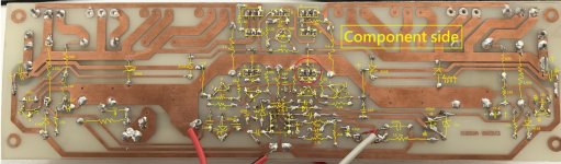
I changed the board. the result is same as before. but DC output reduced from 14mV to 4mV.
Could it be cause of cap type?
I used mkt instead of Ceramic Multilayer and Polyester.
hfe(s) of some transistors is higher than datasheets numbers.

Two things. You should earth your heatsink, not doing so can cause all kinds of minor funnies. But I don't think that's your problem here. Is your 4mV offset rock solid or does it wander about a bit? The reason I ask is that you might have low frequency oscillation or "motorboating". This is where a modest oscilloscope would be invaluable.
If your new PCB layout just follow the previous PCB layout then one of the transistor you soldered the wrong pins, fix it to see if it can work properly.
For diy amp project, I usually omit all the the protection in the amp circuit for pure audio sound and built a kind of uPC1237 speaker protection circuit instead.
For diy amp project, I usually omit all the the protection in the amp circuit for pure audio sound and built a kind of uPC1237 speaker protection circuit instead.
Attachments
Two things. You should earth your heatsink, not doing so can cause all kinds of minor funnies. But I don't think that's your problem here. Is your 4mV offset rock solid or does it wander about a bit? The reason I ask is that you might have low frequency oscillation or "motorboating". This is where a modest oscilloscope would be invaluable.
Yes you're right,I connect the ground to heatsink. It wasn't stable.
How big are the capacitors in your power supply?
They are 4700uF. but I'll change them to 10000uF.
If your new PCB layout just follow the previous PCB layout then one of the transistor you soldered the wrong pins, fix it to see if it can work properly.
For diy amp project, I usually omit all the the protection in the amp circuit for pure audio sound and built a kind of uPC1237 speaker protection circuit instead.
Thanks a lot Patrick. It works very nice. But one more thing, The output DC increased to 93mV. Could it be cause of my mistake that damaged to components?
Yeah me too. Isn't MOSFETs protection better?
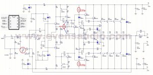
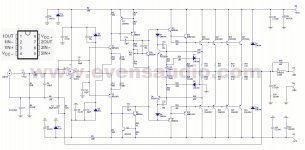
Other parts should be OK. For output DC voltage, you can add a 100uF in the feedback network circuit and some other caps to improve amp stable
Should I prefer MKT cap to use?
I hear a hum sound. Is that because of DC output? Or power supply noise? and how to fix it?
All the best.
Edit:
Isn't MOSFETs protection better than relay?
Last edited:
100n MKT cap ok, 220p normal cap also ok
hum sound maybe no good transfomer, small supply capacitors and no ground plate, when you built the amp with case, good supply capacitors and transfomer, it maybe reduce to minimum or zero
hum sound maybe no good transfomer, small supply capacitors and no ground plate, when you built the amp with case, good supply capacitors and transfomer, it maybe reduce to minimum or zero
Isn't MOSFETs protection better than relay?
Yes, MOSFETs protection is much better
100n MKT cap ok, 220p normal cap also ok
hum sound maybe no good transfomer, small supply capacitors and no ground plate, when you built the amp with case, good supply capacitors and transfomer, it maybe reduce to minimum or zero
Okay thank you. and last question what are these cap for?

bypass cap - A bypass capacitor is a capacitor that shorts AC signals to ground, so that any AC noise that may be present on a DC signal is removed, producing a much cleaner and pure DC signal
I'm not pro educated, just many years of diyer, correct me if I'm worng
I'm not pro educated, just many years of diyer, correct me if I'm worng
Please consider this, and the failure modes before you touch a live circuit. You are more valuable alive than dead.
I find I start to get small shocks at +/-45 volt rails.
Depends on conductivity of your skin.
You need to look around the circuit for voltages with DMM or scope and see if they make sense.
Those long leads on output wont help but should be ok for testing.
Be careful setting bias with no heat sink on outputs, you could cook them.
bypass cap - A bypass capacitor is a capacitor that shorts AC signals to ground, so that any AC noise that may be present on a DC signal is removed, producing a much cleaner and pure DC signal
I'm not pro educated, just many years of diyer, correct me if I'm worng
Thanks a lot,
Amplifier is working well, I used a TL072 wich input offset is 3mV.
It's connected to PC. but I still have noise related to GPU load and Interface.
After replace it with OPA2134 noise got lower, But I got distortion at high frequencies at any volume.
I find I start to get small shocks at +/-45 volt rails.
Depends on conductivity of your skin.
You need to look around the circuit for voltages with DMM or scope and see if they make sense.
Those long leads on output wont help but should be ok for testing.
Be careful setting bias with no heat sink on outputs, you could cook them.
For test I used a low voltage transformator.
Thanks I'll change them.
Yes, I connected them to large heatsink.
It's connected to PC. but I still have noise related to GPU load and Interface.
After replace it with OPA2134 noise got lower, But I got distortion at high frequencies at any volume.
The amp should be ok for audio purpose. If you connected to PC and have noise and distortion, it's hard to determine the cause
The amp should be ok for audio purpose. If you connected to PC and have noise and distortion, it's hard to determine the cause
by connect the amp to the phone and using OPA2134 distortion is still exist.
Can i replace it with LM833N?
Looks likeThanks a lot,
Amplifier is working well, I used a TL072 wich input offset is 3mV.
It's connected to PC. but I still have noise related to GPU load and Interface.
After replace it with OPA2134 noise got lower, But I got distortion at high frequencies at any volume.
1. OPA2134 is not working right and
2. You've got a ground loop between PC and amplifier. (I presume you built it as an IEC Class I device? Well, hi-fi gear typically is Class II for a reason...)
by connect the amp to the phone and using OPA2134 distortion is still exist. Can i replace it with LM833N?
It has no big difference for you to change any op-amp, if TL072 can't do it right, then others op-amp will be almost the same.
I'm not sure what is your current amp setup and connection condition, but for a power amp, it should work with a preamp before any input sources
Looks like
1. OPA2134 is not working right and
2. You've got a ground loop between PC and amplifier. (I presume you built it as an IEC Class I device? Well, hi-fi gear typically is Class II for a reason...)
Yes, and by TL072 I don't have distortion at high frequencies.
I used 10R and 47nF cap to solve it but it didn't.
You're right, I should do something for this.
It has no big difference for you to change any op-amp, if TL072 can't do it right, then others op-amp will be almost the same.
I'm not sure what is your current amp setup and connection condition, but for a power amp, it should work with a preamp before any input sources
OK,right now I'm searching to find a high quality preamp and close to perfect as possible.
You should have the transistors planned to be tied to the heatsink really tied to the heatsink..... Do not leave them in open air. Besides the SOAR limitations even at low power, there is a reason for some of the drivers/ gain stage to be in the same heatsink which is thermal compensation. I didn't test this design but many others are very sensitive to thermal drift/ compensation. Try it again with everything properly mounted. You don't necessarily need all the output transistors mounted, but whatever quantity you decide to wire, keep them tied to the heatsink always...
- Home
- Amplifiers
- Solid State
- Problem with Harman Kardon Modified Clone