I recently built this adjustable dual tracking power supply for test projects. It uses the LM317 and LM337 regulators. The positive side is controlled with a 5K pot giving 1.2 to 16V. The negative side follows the positive side via the op amp. It tracks quite well with the positive and negative voltage being within 10-20 mV. The problem is at the low end. Once the negative side reaches -3.22V it stops tracking the positive voltage. I put the circuit on LT Spice and sure enough the negative side also stops tracking at under -3V so there is something wrong in the design that I seem to be missing. Any help would be appreciated.
Attachments
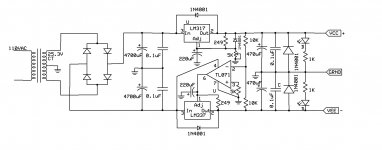
The problem is that the OP-amp is powered from between ground and the negative supply. The non-inverting input is connected to ground and the inverting will be at ground potential through the 2*10k voltage divider. This means that as far as the opamp is concerned both inputs are at Vcc.
Unfortunately the TL71 isn't designed to work with the inputs at rail voltage, so it will be unpredictable. You'll need to bring Vcc up a few volts above ground to make it work.
Unfortunately the TL71 isn't designed to work with the inputs at rail voltage, so it will be unpredictable. You'll need to bring Vcc up a few volts above ground to make it work.
hello.
............and have a look at the four rectifier diodes,i think there is something wrong.
greets
............and have a look at the four rectifier diodes,i think there is something wrong.
greets
Thanks runebrin. I see the problem now. When the regulator is at it's lowest voltages, the output of the opamp must approach ground. The Vcc for this opamp is at ground and the TL071 can't output rail to rail so it stops tracking. If I switch Vcc for the opamp from ground to the positive rail everything works fine and it will track from 1.2 up to 16V.
Sorry mjf, diodes in the bridge are just drawn wrong.
Sorry mjf, diodes in the bridge are just drawn wrong.
Attachments

Last edited:
The same i made with a OP27. If not connected to the load everything is perfect!
But as soon as connected to the load there is a difference from about 120mV!
Pos. 18V43 Neg.18V31 Is this perhaps possible because the pos.side asking 32mA and
the neg.side asks 42mA from the load? I hope someone knows the answer! Without this
powertracking there was a difference from about 1-2mV by a +/- 18V500! Perhaps i must forget this technik!
Shalom - I'm in the process of collecting parts to build essentially the same thing.
Even if you are using 1% resistors for your 10K-10K voltage divider into the inverting pin of the TL071 (OP27 in your case), that still gives
(0.01)(18 +18)(10K/20K) = 180 mV.
So at 120mV you are actually still less than what could happen. I'm not sure a TLE2426 rail splitter would do any better. The specs seem to show a +/-200mV error at 40 volts. You are using +/-18v rails = 36v if I'm understanding right.
One thing that might help is to use the opamp offset pins if you would consider trying a TL071. Bolt a 100K trimpot between pins 1 and 5, then connect the wiper to the negative rail. That will let you change the balance and possibly zero out the downstream output offset.
This is where using the TLE2426 instead of the resistors might pay off. It will probably be more temperature stable, so that once you null the offset it may actually stay that way awhile. I'm using a TL071 and am planning on trying the trimpot.
The difference could also be due to the tolerance of the two LMs. After all, their minimum output voltage is never exactly 1.25volts.
Gajanan Phadte
Gajanan Phadte
A self-centering dual rail circuit
I've come up with a modification to the circuit which seems to be working quite well - I bread-boarded it this evening and tested it. Hopefully the schematic will come through on the posting here. Rather than the op-amp only adjusting the negative supply to match the positive, now the op amp adjusts both the positive and negative voltages to self-center them. The op amp isn't acting as a virtual ground here. Rather it raises one regulator ADJ pin the necessary mV and drops the other a corresponding amount.
I have the supply designed to output +/- 6.36v, which will be 4.5v RMS feeding an amp, which works out to be 450mW into my 500mW capable Shure SDH-840s. 🙂 Those two wall warts (got them for $1 each on surplus) output 20VDC at 750mA, with internal 2200uF caps and 470 ohm bleed resistors as shown.
To test it I grounded the op amp output wire, which reverts the circuit to the standard datasheet configuration for dual rail 327/337. I measured V+ 6.24v and V- 6.20v, a 40 mV difference. Measuring the resistive divider (I used 1% 1Ks) gave 20mV, as expected - half the offset error.
Then I ungrounded the connection and connected the op amp. Both outputs at 6.22! (v+ = 6.22 and V- = -6.22 of course). Actually V- was occasionally flipping between 6.22 and 6.21. Time to adjust the trimmer pot. I measured 1.4mV between the resistive divider and ground. 1.75 turns of the 25-turn trimmer zeroed that completely out, at least to the accuracy of my meter. And sure enough, no more 10mV flipping on V-. Solid at -6.22.
One thing that led me to come up with the circuit was realizing a negative-only op amp would have a hard time adjusting for unbalanced loads. If a big load was dumped on V+ to ground it may adjust OK, but if a similar load was just put on V- to ground (and the 337 drop increased) probably not. This symmetrical self-centering circuit shouldn't care. To test that I'm going to put a 200mA load just on V+ to ground tomorrow and see if the rails stay centered.
Parts:
C1,C2 = 0.1uf 35v tantalum as per 317 data sheet
R1,R2 bleed resistors, 22K 1/4W 5%
D1,D2,D3,D4,D7,D8,D9,D10 protection diodes = 1N4003 200v 1A
D5,D6 = 12v 1W zener diodes, NTE 142A
R3,R4 = 2 1k 1/4W 5% in parallel to handle the wattage, or just use a 1/2W 470 ohm.
U1 = LM317
U2 = LM337
U3 = TL071
R9 = 100K 25 turn trimpot
C3,C4 = 10uf 35V tantalum, as per the 317 datasheet
R5,R7 = 220 ohm 1/4W 1%
R6,R8 = 1% 560 ohm and 330 ohm in series to get 890. 1/4W
R11,R12 = 1K 1/4W 1%
R10 = 470 ohm, 1%
C5,C6 = 1000 uF 35v aluminum electros
C7,C8 = 1uf 35v tantalum, as per the 317 data sheet
R13,R14 = 1.5K 1/4W 5% load resistors
Hello agdr and gmphadte,
Many thanks for responding! And a apology for my so called late reaction!
Later, i think next week (i'm very busy at this moment) i will write my solution to this topic. Only i can say at this time: it is working very very nice! With a tolerance within 1mV between neg.18V5 and pos.18V5!!!
So long!
Shalom
- Status
- Not open for further replies.
- Home
- Amplifiers
- Power Supplies
- Problem with dual tracking power supply